
In-place motor assembly determination system and method based on intelligent camera

A smart camera and judgment method technology, applied in general control system, control/adjustment system, electrical program control, etc., can solve problems such as difficulty in ensuring accuracy, and achieve the effect of avoiding negligence and improving assembly accuracy

Active Publication Date: 2020-02-14
AEROSPACE HI TECH HLDG GROUP
View PDF12 Cites 0 Cited by
  • Summary
  • Abstract
  • Description
  • Claims
  • Application Information

AI Technical Summary

Problems solved by technology

[0004] The present invention is to solve the problem that the existing judging whether the motor for controlling the swing of the pointer in the automobile meter is in place is recognized by human eyes, and it is difficult to ensure the accuracy. Now, a system and method for judging the motor assembly in place based on an intelligent camera are provided.

Method used


Image

  • In-place motor assembly determination system and method based on intelligent camera
  • In-place motor assembly determination system and method based on intelligent camera

Examples


specific Embodiment approach 1

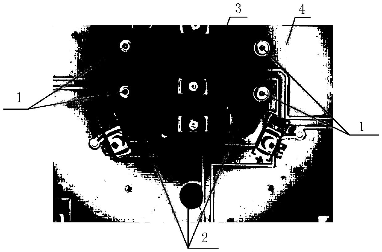
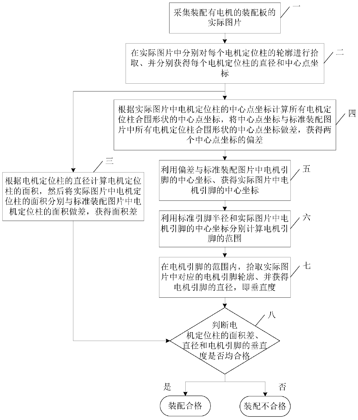
[0048] Specific implementation mode one: refer to figure 1 with figure 2 This embodiment is specifically described. The smart camera-based motor assembly-in-place determination method described in this embodiment includes the following steps:

[0049] Step 1: Use the smart camera to collect the actual picture of the assembly board 4 equipped with the motor;

[0050] Step 2: In the actual picture, by picking the color of the motor positioning post 2, obtain the contours of the three motor positioning posts 2 respectively, which are circular, and calculate and obtain the diameter and center point coordinates of each motor positioning post 2 respectively, Then perform steps 3 and 4 at the same time;

[0051] Step 3: Calculate the area of ​​each motor positioning post 2 according to the diameter of each motor positioning post 2, and then compare the area of ​​each motor positioning post 2 in the actual picture with the area of ​​the corresponding motor positioning post 2 in the...

specific Embodiment approach 2

[0063] Specific implementation mode two: refer to figure 1 This embodiment is described in detail. The smart camera-based motor assembly in-position determination system described in this embodiment includes the following units:

[0064] Acquisition unit: collect the actual picture of the assembly board 4 equipped with the motor;

[0065] Motor positioning column parameter acquisition unit: in the actual picture, by picking up the color of the motor positioning column 2, obtain the outline of each motor positioning column 2, which is circular, and obtain the diameter and center point of each motor positioning column 2 respectively coordinate;

[0066] Motor positioning post area difference acquisition unit: Calculate the area of ​​each motor positioning post 2 according to the diameter of each motor positioning post 2, and then compare the area of ​​each motor positioning post 2 in the actual picture with the corresponding motor positioning in the standard assembly picture T...


PUM


Abstract

The invention, which relates to the field of automobile instrument assembling, discloses an in-place motor assembly determination system and method based on an intelligent camera, thereby solving a problem that the accuracy is difficult to guarantee because whether a motor for controlling a pointer to swing in an automobile instrument is arranged in place or not is judged by naked eyes. Accordingto the invention, the intelligent camera is used for collecting the actual picture of the assembly plate, and then the parameters of a motor positioning column and a pin in the picture are determinedaccording to the picture, so that whether the assembly is qualified or not is determined; and the precision of the determination can reach 0.1mm, so that the manual misjudgment or negligence caused byfatigue can be avoided. The assembly accuracy is effectively improved, and a basis is provided for later product tracing.

Description

technical field [0001] The invention belongs to the field of assembly of automobile instruments, and in particular relates to the assembly of a motor for driving instrument pointers. Background technique [0002] Under the background that the country vigorously advocates intelligent manufacturing, the automotive instrument industry is also improving automatic assembly. Pointer indication is the most important type of equipment in automobile instrumentation. It mainly relies on the motor to drive the pointer to swing. Therefore, the judgment of whether the motor assembly is in place will directly affect the function of the instrument. [0003] In the existing operation process, whether the motor assembly is in place depends on the staff to judge with the naked eye, but this method is affected by the ability and responsibility of the personnel, and it is difficult to achieve the purpose of accurate judgment. Contents of the invention [0004] The present invention aims to s...

Claims


Application Information

Patent Timeline
Patent Type & Authority Applications(China)
IPC IPC(8): G05B19/19
CPCG05B19/19G05B2219/35349
Inventor 卜家洛肖芳慧高成鼎李占双金佳鑫
Owner AEROSPACE HI TECH HLDG GROUP
Learn More