Hot air supplying head for transferring micro LED and micro LED transferring system

A technology of micro light-emitting diodes and transfer heads, which is applied in the direction of electrical components, semiconductor/solid-state device manufacturing, circuits, etc. It can solve the problems of scattered alignment, continuous use of adhesives, damage, etc., and achieve an effective transfer effect

Pending Publication Date: 2020-02-14
POINT ENG
View PDF5 Cites 2 Cited by
  • Summary
  • Abstract
  • Description
  • Claims
  • Application Information

AI Technical Summary

Problems solved by technology

Compared with the electrostatic head method, the method does not have the problem of micro-LED damage, but has the following disadvantages: in the transfer process, only when the adhesive force of the elastic transfer head is greater than the adhesive force of the target substrate can the micro-LED be transferred stably. An additional process for forming electrodes is required
However, Conventional Invention 4 has the following disadvantages: the adhesive needs to be continuously used, and the micro LED is also damaged when the roller is pressed
However, the existing invention 5 has the following disadvantages: in terms of immersing the micro LED in the solution to transfer to the array substrate, an additional solution is required, and a drying process is required thereafter
However, Conventional Invention 6 has the following disadvantages: it is a method of transferring micro LEDs by applying a bonding substance with adhesive force on the bonding surfaces of multiple pick-up heads, so an additional process of applying a bonding substance to the pick-up heads is required.
However, in order to transfer the heat, the transfer head needs to be in contact with the micro LED, which causes problems such as damage due to contact, alignment disorder, etc., and there is a need to have an additional micro LED to prevent it from becoming a non-adsorption object. The problem of the concave part of the contact
[0014] In order to solve the problems of the existing inventions as described above, it is necessary to directly adopt the basic principles adopted by the existing inventions while improving the above-mentioned shortcomings, but the above-mentioned shortcomings are derived from the basic principles adopted by the existing inventions, so There is a limit to improving the shortcomings while maintaining the fundamentals

Method used


Image

  • Hot air supplying head for transferring micro LED and micro LED transferring system
  • Hot air supplying head for transferring micro LED and micro LED transferring system
  • Hot air supplying head for transferring micro LED and micro LED transferring system

Examples


Embodiment Construction

[0054] The following merely illustrates the principles of the invention. Therefore, although not explicitly described or illustrated in this specification, those skilled in the art can realize the principle of the invention and invent various devices included in the concept and scope of the invention. In addition, it should be understood that all conditional terms and examples listed in this specification are only for clearly understanding the concept of the invention in principle, and are not limited to such specifically listed examples and states.

[0055] The above-mentioned purpose, features, and advantages will become more apparent from the following detailed description related to the accompanying drawings, so those skilled in the art to which the invention pertains can easily implement the technical idea of ​​the invention.

[0056] Embodiments described in this specification will be described with reference to cross-sectional views and / or perspective views which are id...


PUM


Abstract

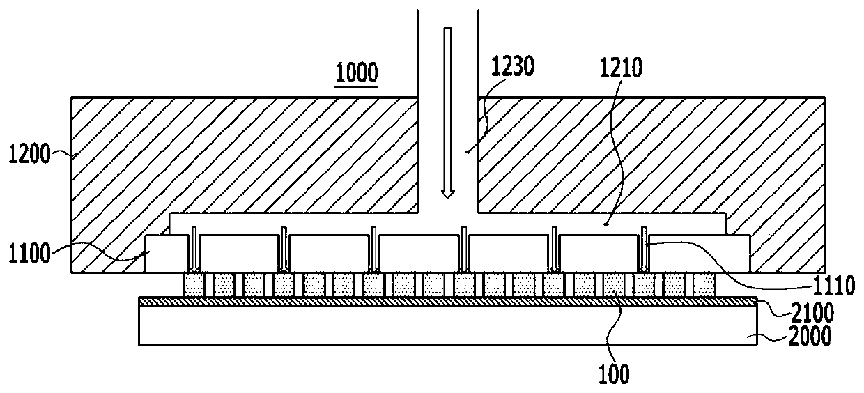
The present invention relates to provide a hot air supplying head for transferring a micro LED and a micro LED transfer system using the same, the hot air supplying head effectively transferring microLEDs.

Description

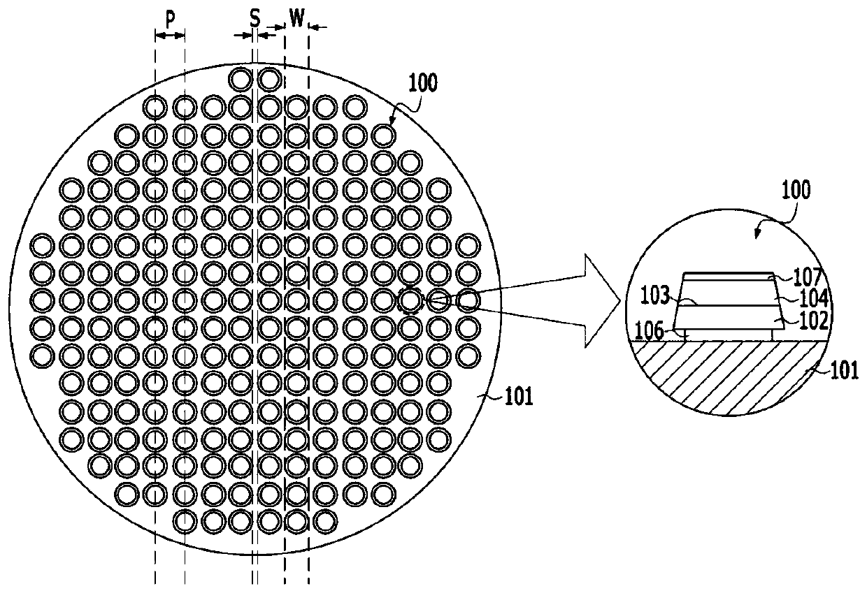
technical field [0001] The invention relates to a hot air head for transferring micro-light emitting diodes (Light Emitting Diode, LED) and a micro-LED transfer printing system using the same. Background technique [0002] Currently, liquid crystal display (LCD) is still the mainstream in the display market, but Organic Light Emitting Diode (OLED) is rapidly replacing LCD and gradually becoming the mainstream. Recently, as display companies are actively participating in the OLED market, micro (Micro) light-emitting diode (hereinafter referred to as "micro LED") displays are gradually becoming the next-generation display. The core raw materials of LCD and OLED are liquid crystal (Liquid Crystal) and organic materials, respectively. On the contrary, micro-LED display is a display that uses LED chip itself as a light-emitting material in micron (μm) units. [0003] Since the Cree company applied for a patent on "micro-light-emitting diode arrays that increase light output" (Ko...

Claims


Application Information

Patent Timeline
Patent Type & Authority Applications(China)
IPC IPC(8): H01L21/67H01L33/00
CPCH01L21/67144H01L33/0095H01L21/67784H01L21/6838
Inventor 安范模朴胜浩边圣铉
Owner POINT ENG
Why Eureka
Try Eureka