Communication equipment
A technology for communication equipment and radio frequency signals, which is applied in the direction of antenna equipment with additional functions, antenna, antenna grounding switch structure connection, etc., can solve the problem of increasing difficulty in the design of communication equipment shells, and reduce the number of electronic devices and reduce radiation The setting of the body, the effect of the exquisite structure
- Summary
- Abstract
- Description
- Claims
- Application Information
AI Technical Summary
Problems solved by technology
Method used
Image

Examples
example 1
[0099] This example provides a communication device consisting of:
[0100] The floor of the motherboard, the feed structure, the excitation unit, the matching network, and the capacitive load; and the floor of the motherboard, the feed structure, the excitation unit, and the matching network resonate.
[0101] The matching network here may correspond to the first inductive matching component, the second inductive matching component, the third inductive matching component, or the fourth inductive matching component and so on.
[0102] The feeding structure at least includes: a feeding source.
[0103] For example, after the floor of the motherboard, the feed structure, and the excitation unit are electrically connected, they will resonate with the matching network to generate the resonance in the required 6G frequency band, and the signal is mainly radiated by the floor of the motherboard. The motherboard needs clearance in the area where the feed structure and the excitation ...
example 2
[0106] This example provides two antennas based on the communication device provided in Example 1. Two antennas are provided, which are:
[0107] Coupling feed antenna;
[0108] Loop (loop) radiating antenna.
[0109] The following describes the two implementation antennas respectively:
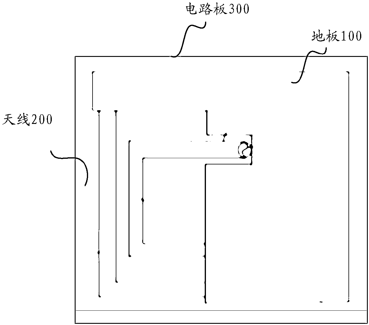
[0110] Coupling feed antennas can be as Figures 1 to 4 shown, including:
[0111] The excitation unit excites the floor of the motherboard to radiate radio frequency signals.
[0112] The loop conforms to the antenna and can be as Figure 5 to Figure 9 shown. exist Figure 9 The arrow in the figure indicates that the path forms a ring, and the ring can excite the floor of the motherboard to radiate radio frequency signals.
example 3
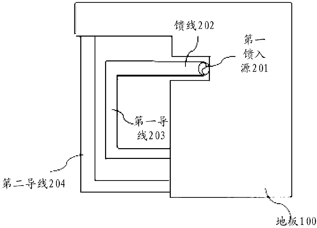
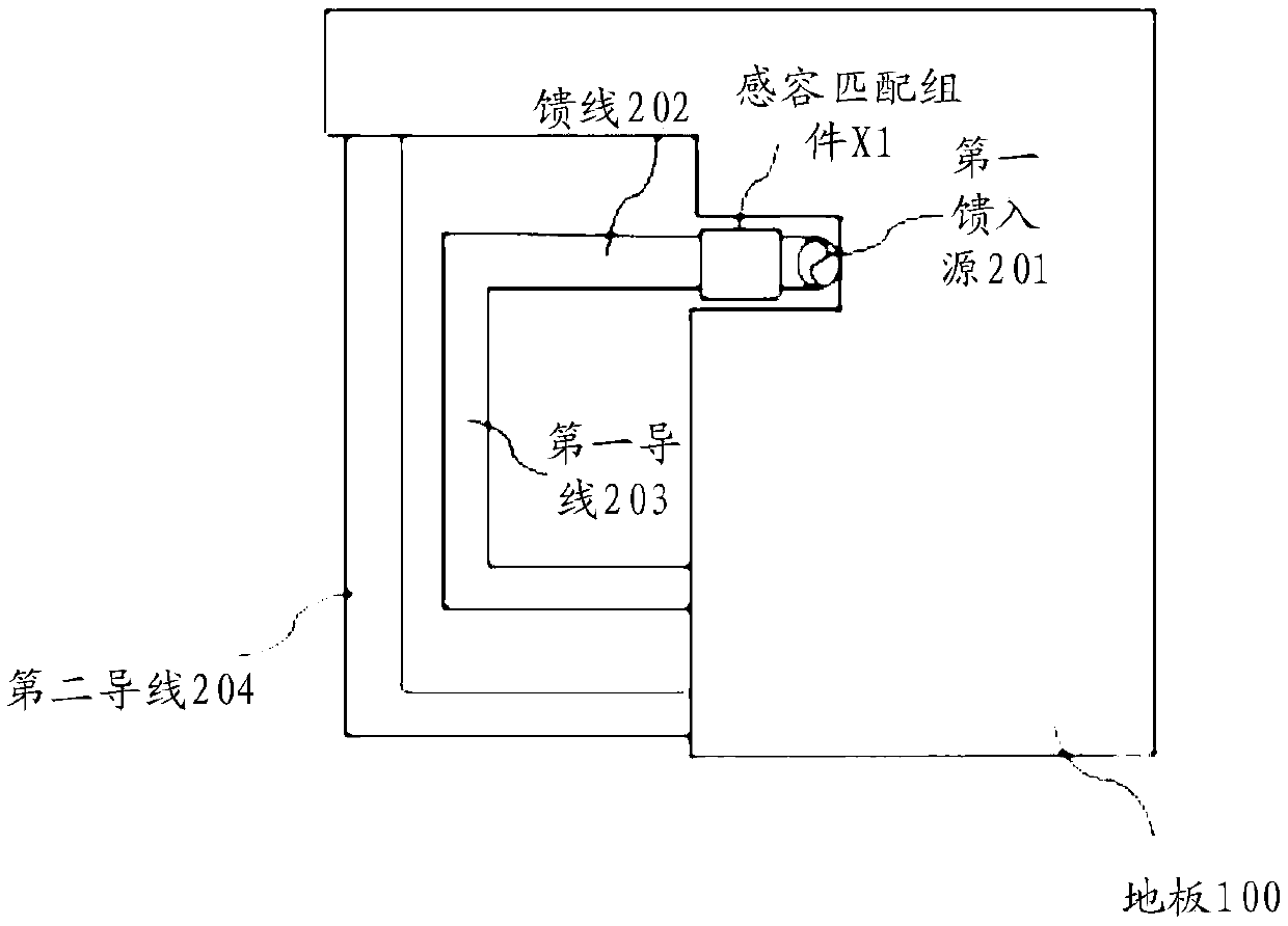
[0114] image 3 shows the floor as the main board, which acts as the floor radiator;
[0115] The first feed-in source is used as the output and input port of the antenna signal, and is connected with the radio frequency circuit;
[0116] The first inductance-capacitance matching component can also be used as the capacitive load of the antenna;
[0117] The first wire is connected to the first inductance-capacitance matching component;
[0118] the second wire and the third wire. The first wire, the first inductance-capacitance matching component, the second wire 2 and the third wire are combined to form an antenna feed structure and the floor of the main board to form a radiation body of the antenna.
PUM
 Abstract
Description
Claims
Application Information
 - R&D
- Intellectual Property
- Life Sciences
- Materials
- Tech Scout
- Unparalleled Data Quality
- Higher Quality Content
- 60% Fewer Hallucinations
Browse by: Latest US Patents, China's latest patents, Technical Efficacy Thesaurus, Application Domain, Technology Topic, Popular Technical Reports.
© 2025 PatSnap. All rights reserved.Legal|Privacy policy|Modern Slavery Act Transparency Statement|Sitemap|About US| Contact US: help@patsnap.com