Snow removal device for high-altitude power lines

A high-altitude power and power line technology, applied in overhead installation, cable installation, electrical components, etc., can solve the problems of power line safety hazards, grid failures, high design costs and maintenance costs, and achieve low cost, simple structure, and easy promotion. Effect

Active Publication Date: 2020-02-14
GUANGXI POWER GRID ELECTRIC POWER RES INST +1
View PDF7 Cites 5 Cited by
  • Summary
  • Abstract
  • Description
  • Claims
  • Application Information

AI Technical Summary

Problems solved by technology

[0002] For high-altitude power lines, snow often occurs on the upper part of the power lines in winter. If the amount of snow accumulation is large, the power lines are likely to be broken, causing power grid failure, and causing the falling power lines to cause a greater safety hazard
[0003] At present, most traditional cables use special snow cleaning robots, electric heating or electromagnetic oscillation to remove snow. When these methods are actually used, they are technically difficult to implement, high in design and maintenance costs, high in failure rate, and inconvenient. maintenance, so it cannot be widely used

Method used


Image

  • Snow removal device for high-altitude power lines
  • Snow removal device for high-altitude power lines
  • Snow removal device for high-altitude power lines

Examples


Embodiment 1

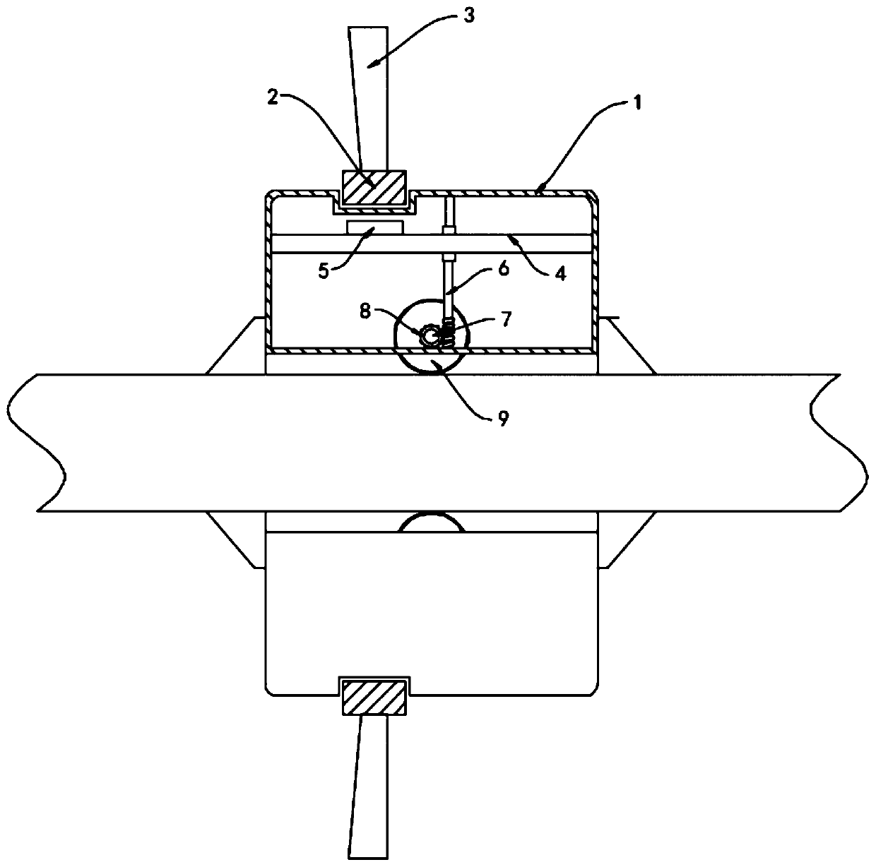
[0017] Such as figure 1 As shown, a snow removal device for high-altitude power lines includes an annular casing 1 sleeved outside the power line, and a slip ring 2 is rotatably connected to the outside of the annular casing 1. The slip ring 2 consists of two magnetic halves connected end to end and opposite in magnetic Composed of circular rings, the outer wall of the slip ring 2 is equidistantly arranged with a plurality of fan blades 3 in the circumferential direction, and the inner wall of the annular housing 1 is slidably connected with a horizontally arranged lifting plate 4, and the upper surface of the lifting plate 4 is fixedly connected. Permanent magnet block 5 is arranged.

[0018] In this embodiment, a worm 6 is rotatably connected to the inner side wall of the annular housing 1, and the upper half of the worm 6 is provided with threads, and the upper end of the worm 6 passes through the lifting plate 4 and is threadedly connected with the lifting plate 4. The ann...

Embodiment 2

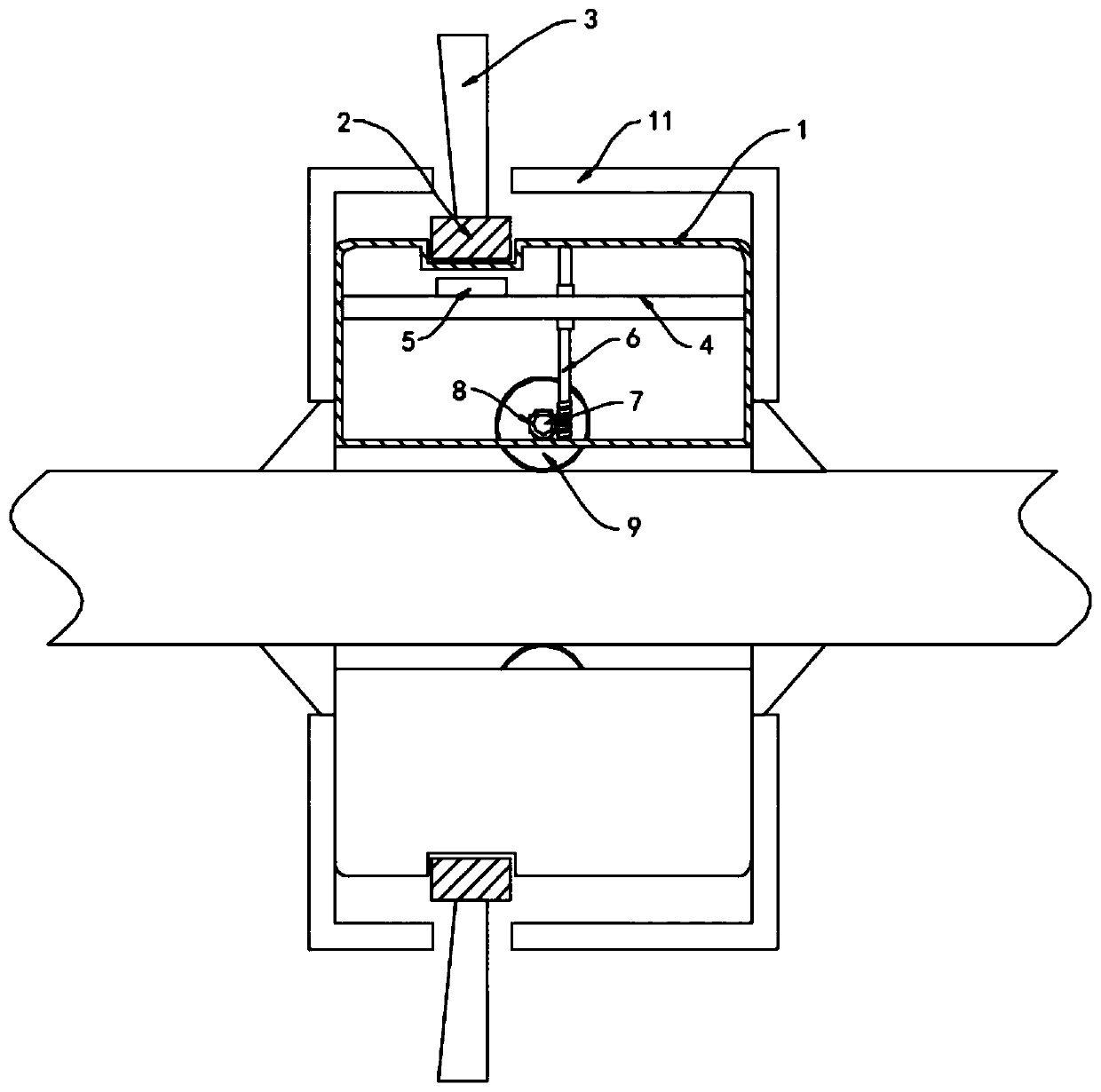
[0021] Such as figure 2 As shown, the difference between this embodiment and Embodiment 1 is that a plurality of guide pipes 11 are arranged on the side wall of the annular housing 1, and the lower ends of the guide pipes 11 extend to the top of the snow removal plate 10, and the guide pipes The upper end of the pipe 11 is extended to the fan blade 3 and arranged there.

[0022] In this embodiment, the upper end of the guide tube 11 is extended to the fan blade 3. When the snow removal plate 10 slides on the power line, the snow accumulated on the power line is scraped off to the surface of the snow removal plate 10, and the snow is passed through the flow guide. The pipe 11 is transported to the fan blade 3, and the fan blade 3 rotates, and under the action of centrifugal force, the accumulated snow is thrown around to prevent the accumulated snow from rising and attaching to the power line again, and the snow removal effect is better.

Embodiment 3

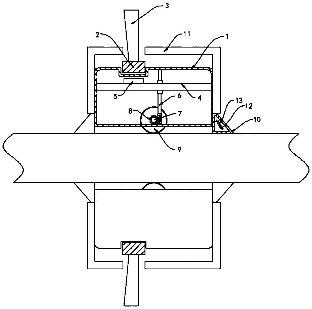
[0024] Such as image 3 As shown, the difference between this embodiment and Embodiment 1 lies in that: the snow removal plate 10 is provided with a cavity 12, and the cavity 12 is provided with a heating coil 13, and the snow removal plate 10 is made of a heat-conducting material.

[0025] In this embodiment, according to the principle of electromagnetic induction, when the closed coil moves to cut the magnetic induction line, an induced current is generated in the coil, and because there is a current passing through the power line, a magnetic field is formed outside the power line, and the snow removal plate 10 drives the heating coil 13 in the When the power line slides back and forth, the heating coil 13 cuts the magnetic induction line to generate an induced current and heat, which heats the snow removal plate 10 to melt the snow accumulated on the snow removal plate 10, further improving its snow removal effect.


PUM


Abstract

The invention belongs to the field of electric power equipment and especially relates to a snow removal device for high-altitude power lines. The device of the invention includes an annular housing which sleeves a power line. A slip ring is rotationally connected to the outside of the annular housing. The slip ring is composed of two magnetic semi-circular rings which are connected end to end andhave opposite magnetism. Multiple fan blades are equally-spaced in the circumferential direction on the outer sidewall of the slip ring. A horizontally-arranged lifting plate is slidably connected tothe inner sidewall of the annular housing. A permanent magnet block is fixedly connected to the upper surface of the lifting plate. A worm is rotationally connected to the inner side wall of the annular housing. The upper half part of the worm is provided with thread, and the upper end of the worm penetrates through the lifting plate and is in threaded connection with the lifting plate. A rotatingshaft is rotationally connected to the inner side wall of the annular housing. The rotating shaft is coaxially and fixedly sleeved with a worm wheel and a roller. The fan blades are driven to rotateby wind force, and then a snow removal plate can be driven to slide back and forth on the power line, so that the snow on the power line can be scraped off. The device of the invention has a simple structure, is low-cost, and is convenient for promotion.

Description

technical field [0001] The invention belongs to the field of power equipment, in particular to a snow removal device for high-altitude power lines. Background technique [0002] For high-altitude power lines, snow often occurs on the upper part of the power lines in winter. If the amount of snow accumulation is large, the power lines are likely to be broken, causing grid failure, and the falling power lines will cause a greater safety hazard. [0003] At present, most traditional cables use special snow cleaning robots, electric heating or electromagnetic oscillation to remove snow. When these methods are actually used, they are technically difficult to implement, high in design and maintenance costs, high in failure rate, and inconvenient. Maintenance, so it cannot be widely used. [0004] For this reason, we propose a kind of snow removal device for high-altitude power line to solve the above problems. Contents of the invention [0005] The object of the present invent...

Claims


Application Information

Patent Timeline
IPC IPC(8): H02G7/16
CPCH02G7/16
Inventor 刘远远李文君
Owner GUANGXI POWER GRID ELECTRIC POWER RES INST
Why Eureka
Try Eureka