Supercharge Your Innovation With Domain-Expert AI Agents!

Self-excited push-pull oscillation circuit

A technology of self-excited oscillation and oscillating circuits, applied in power oscillators, electrical components, etc., can solve problems such as increased power consumption, poor circuit stability, and MOS tube damage

Active Publication Date: 2020-02-14
厦门市国维电子科技有限公司
View PDF6 Cites 0 Cited by
  • Summary
  • Abstract
  • Description
  • Claims
  • Application Information

AI Technical Summary

Problems solved by technology

However, there are gaps in the application of multiple units
Because strict synchronization is required between multiple units, even strict synchronization circuits with different ground levels between units, especially when dozens of power units work synchronously, once the synchronization is poor and the power tubes fail to conduct in time, the current will Through the internal body diode, the power consumption is doubled, and the MOS tube is overheated and damaged
Although some can be driven by an isolation transformer, there are problems such as complex circuits, easy deviation of the midpoint of the main power core, and poor circuit stability, so it is difficult to apply in power circuits.

Method used


Image

  • Self-excited push-pull oscillation circuit
  • Self-excited push-pull oscillation circuit
  • Self-excited push-pull oscillation circuit

Examples


Embodiment 1

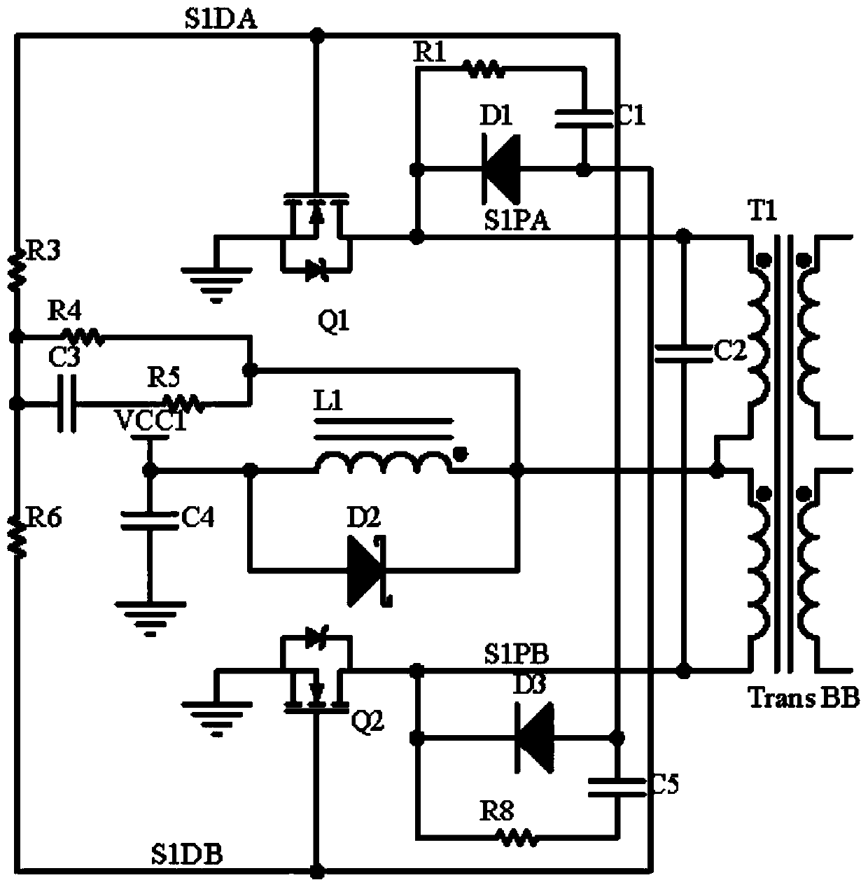
[0016] The self-excited push-pull oscillating circuit of the present invention includes at least two self-excited oscillating unit circuits, each self-excited oscillating unit circuit shares a transformer T1, and the transformer T1 has a magnetic core and at least two groups corresponding to each self-excited oscillating unit circuit Power coils, each group of power coils is wound on the same magnetic core, each group of power coils includes a power coil 1 and a power coil 2, and the power coil 2 in each group adopts a center-tapped coil;

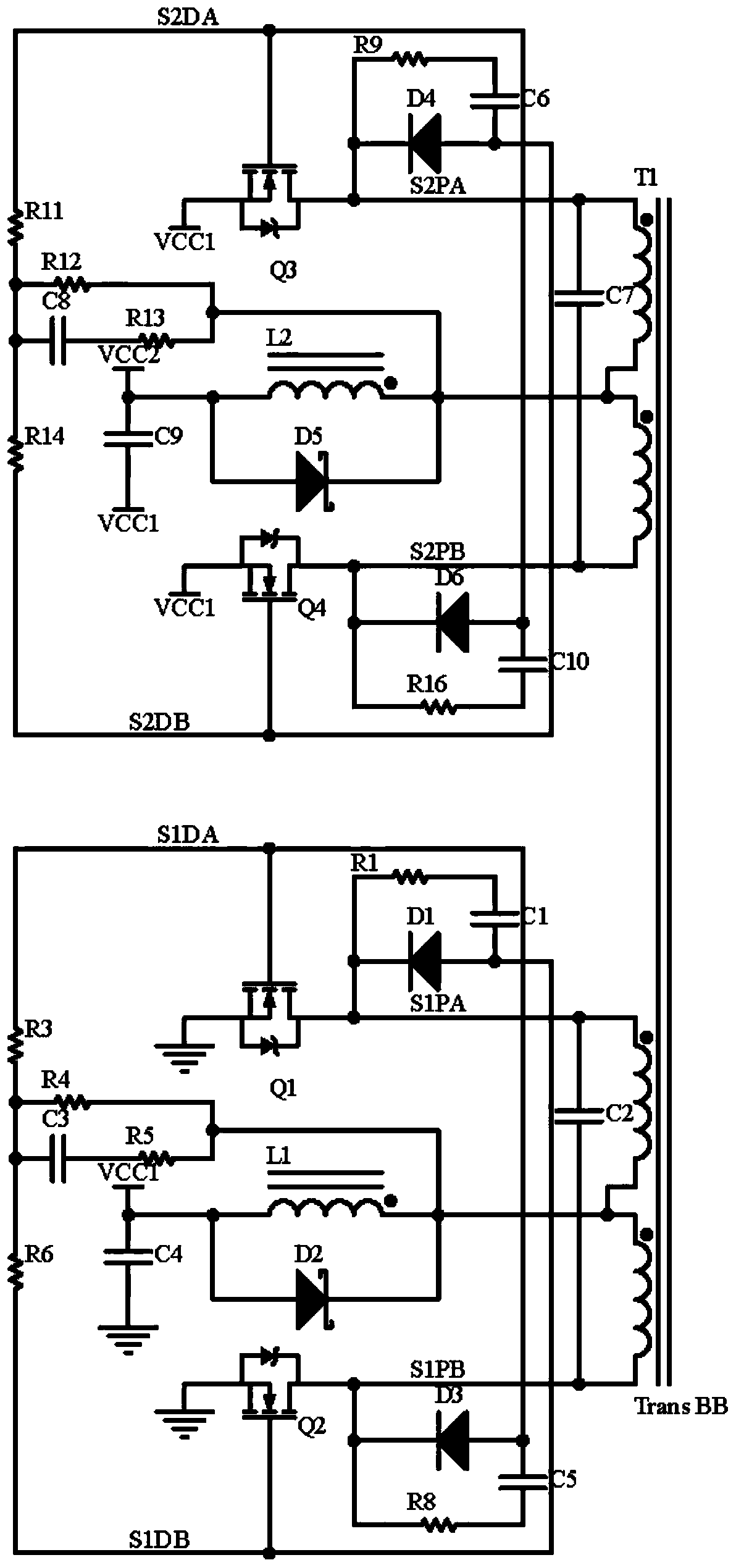
[0017] In this embodiment, the number of self-excited oscillation unit circuits is two, for example, figure 2 As shown, it includes a first self-excited oscillation unit circuit and a second self-excited oscillation unit circuit; the first self-excited oscillation unit circuit and the second self-excited oscillation unit circuit share a transformer T1, and the transformer T1 has a magnetic core, a first power coil, and a , the second power...

Embodiment 2

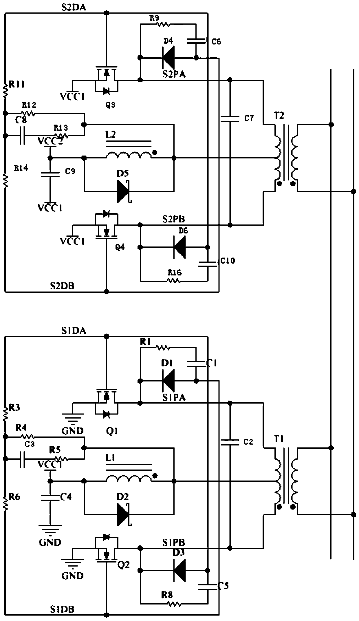
[0025] Such as image 3 As shown, the difference between this embodiment and the first embodiment is that two transformers are used, that is, a transformer T2 is added on the basis of the transformer T1, and the second power coil of the transformer T2 also uses a center-tapped coil. The first self-excited oscillation unit circuit is set corresponding to the transformer T1, the second self-excited oscillation unit circuit is set corresponding to the transformer T2, the power coil 1 and the power coil 2 of the transformer T1 are wound on the magnetic core of the transformer T1, and the power of the transformer T2 The coil 1 and the power coil 2 are wound on the magnetic core of the transformer T2, and both ends of the power coil 1 of the transformer T1 and the power coil 1 of the transformer T2 are connected in parallel.

[0026] In the self-excited push-pull oscillating circuit of the present invention, the signal on the power coil is directly used to control the conduction and...


PUM


Abstract

The invention discloses a self-excited push-pull oscillation circuit, which comprises at least two self-excited oscillation unit circuits sharing the same transformer, and each power coil II of the transformer adopts a coil with a center tap. According to the self-excited push-pull oscillation circuit, signals on the power coils are directly used for controlling connection and disconnection of thepower tubes through the coupling network, and particularly, diodes are respectively arranged for accelerating disconnection of the corresponding power tubes, so that the self-oscillation unit circuits can be synchronized with one another, and the situation that in an asynchronous state, currentflows the internal diodes, power consumption is multiplied, and the self-oscillation unit circuits are heated and damaged is avoided. According to the invention, each self-excited oscillation unit circuit is synchronized through the power coil, the blank of synchronous work of a plurality of self-excited oscillation unit circuits is solved, the units with different levels to ground are strictly synchronized, the circuit connection is very simple, and the units coordinate with each other to work at the optimal working point.

Description

technical field [0001] The invention relates to the field of electronic circuits, in particular to a self-excited push-pull oscillation circuit. Background technique [0002] At present, the existing self-excited push-pull oscillating circuit is used in occasions such as signal generation, DC conversion, and power output, and generally uses a single-unit self-excited oscillating circuit. However, there are gaps in the application of multiple units. Because strict synchronization is required between multiple units, even strict synchronization circuits with different ground levels between units, especially when dozens of power units work synchronously, once the synchronization is poor and the power tubes fail to conduct in time, the current will Through the internal body diode, the power consumption is doubled, and the MOS tube is overheated and damaged. Although some can be driven by an isolation transformer, there are problems such as complex circuits, easy deviation of th...

Claims


Application Information

Patent Timeline
Patent Type & Authority Applications(China)
IPC IPC(8): H03B5/12
CPCH03B5/12
Inventor 蔡维新杨婷婷
Owner 厦门市国维电子科技有限公司
Features
  • R&D
  • Intellectual Property
  • Life Sciences
  • Materials
  • Tech Scout
  • Unparalleled Data Quality
  • Higher Quality Content
  • 60% Fewer Hallucinations
Learn More