Flat bar system

A slat and cover plate technology, applied in the field of cover slat system, can solve problems such as quality degradation and tension, and achieve the effect of simplifying operations

Active Publication Date: 2020-02-14
TRUETZSCHLER GRP SE
View PDF6 Cites 2 Cited by
  • Summary
  • Abstract
  • Description
  • Claims
  • Application Information

AI Technical Summary

Problems solved by technology

The resulting forces are of sufficient magnitude to cause tension in th

Method used


Image

  • Flat bar system
  • Flat bar system
  • Flat bar system

Examples


Embodiment Construction

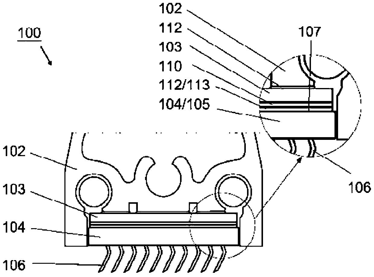
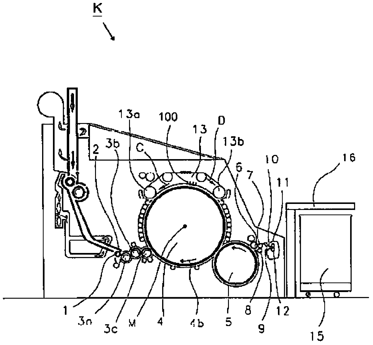
[0025] Refer below Figure 1 to Figure 8 A preferred embodiment of the flat strip system 100 according to the invention, which is intended to be used on a carding machine for cotton, chemical fibers or the like, will be explained. Identical features in the figures are each provided with the same reference numerals. It should be understood here that the drawings are only shown simplified and in particular not to scale.

[0026] figure 1 The cover strip system 100 is shown in cross section. The cover strip system 100 comprises an elongated cover strip 102, which is preferably produced from aluminum. A magnetic element 103 is fastened to the cover strip 102 . On the flat strip 102 a clothing strip 104 with clothing points 106 is mounted adjacent to the magnetic element 103 , ie by using magnetic force, as will now be explained in detail.

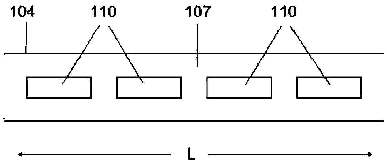
[0027] In the enlarged area additionally shown figure 1 The area on the right of the cross-sectional view. It can thus be seen that the...


PUM


Abstract

The invention relates to a flat bar system (100) for use on a carding machine (K) for cotton, man-made fibers or such like. The flat bar system comprises an elongated flat bar (102) to which a magnetic element (103) is fastened, and an elongated flat top strip (104) which on its rear side (107) facing the flat bar (102) has a rear layer containing a ferrous material. The flat top strip (104) can therefore be detachably fastened to the magnetic element (103) of the flat bar (102) by its rear layer (108), using magnetic force. The rear layer (108) comprises a plurality of segments (110), which each contain a ferrous material, and the segments (110) are spaced apart and uncoupled from each other in the longitudinal direction (L) of the flat top strip (104).

Description

technical field [0001] The invention relates to a flat strip system according to the preamble of claim 1 and the preamble of claim 12 for use on a carding machine for cotton, man-made fibers or the like. Background technique [0002] According to the prior art, it is known in the field of textile technology to attach the clothing strips to the associated flat strips by means of magnetic force in carding machines for processing cotton, man-made fibers or the like. For this purpose, a magnetic element is fastened to the base of the cover strip by means of an adhesive layer. A thin steel sheet is fastened on the rear side of the clothing strip facing the flat strip by means of an adhesive layer. For mounting the clothing strip on the flat strip, the thin steel sheet can be brought into contact or interact with the magnetic element. If the clothing strip needs to be replaced, the clothing strip can be dismantled by overcoming the fixed magnetic force with a suitable tool by me...

Claims


Application Information

Patent Timeline
IPC IPC(8): D01G15/24D01G15/92
CPCD01G15/24D01G15/92
Inventor 马丁·多文安德烈亚斯·泽博德卡
Owner TRUETZSCHLER GRP SE
Why Eureka
Try Eureka