Al technical title is built by PatSnap Al team. It summarizes the technical point description of the patent document.
A pulverizer and shell technology, used in grain processing and other directions, can solve the problems of equipment damage, inconvenient air pulverization, and large shells, and achieve the effects of improving processing accuracy, increasing service life, and improving processing efficiency.
Pending Publication Date: 2020-02-21
ZHEJIANG OCEAN UNIV
View PDF0 Cites 1 Cited by
Summary
Abstract
Description
Claims
Application Information
AI Technical Summary
This helps you quickly interpret patents by identifying the three key elements:
Problems solved by technology
Method used
Benefits of technology
Problems solved by technology
[0002] The basic structure of the shell is mainly divided into three parts. The outermost layer is a cuticle composed of hard protein; the middle is a prism layer composed of calcite or aragonite crystals, which mainly provide hardness and corrosion resistance for the shell; the innermost layer is pearl The layer mainly provides hardness and toughness for shells, and is generally composed of CaCO3 minerals (inorganic phase) such as calcite or aragonite and organic matter (organic phase). Due to the high calcium content of shells, they are used as raw materials for production and need to be crushed. The air pulverizer is a relatively efficient pulverizing device, but the shell is relatively large, which is not convenient for direct air pulverization. It is not only inefficient, but also harmful to the equipment. Therefore, we propose a shell pulverizer
Method used
Image
Click on the blue label to locate the original text in one second.
Reading with bidirectional positioning of images and text.
Examples
Embodiment Construction
[0015] The following will clearly and completely describe the technical solutions in the embodiments of the present invention with reference to the accompanying drawings in the embodiments of the present invention. Obviously, the described embodiments are only some, not all, embodiments of the present invention. Based on the embodiments of the present invention, all other embodiments obtained by persons of ordinary skill in the art without making creative efforts belong to the protection scope of the present invention.
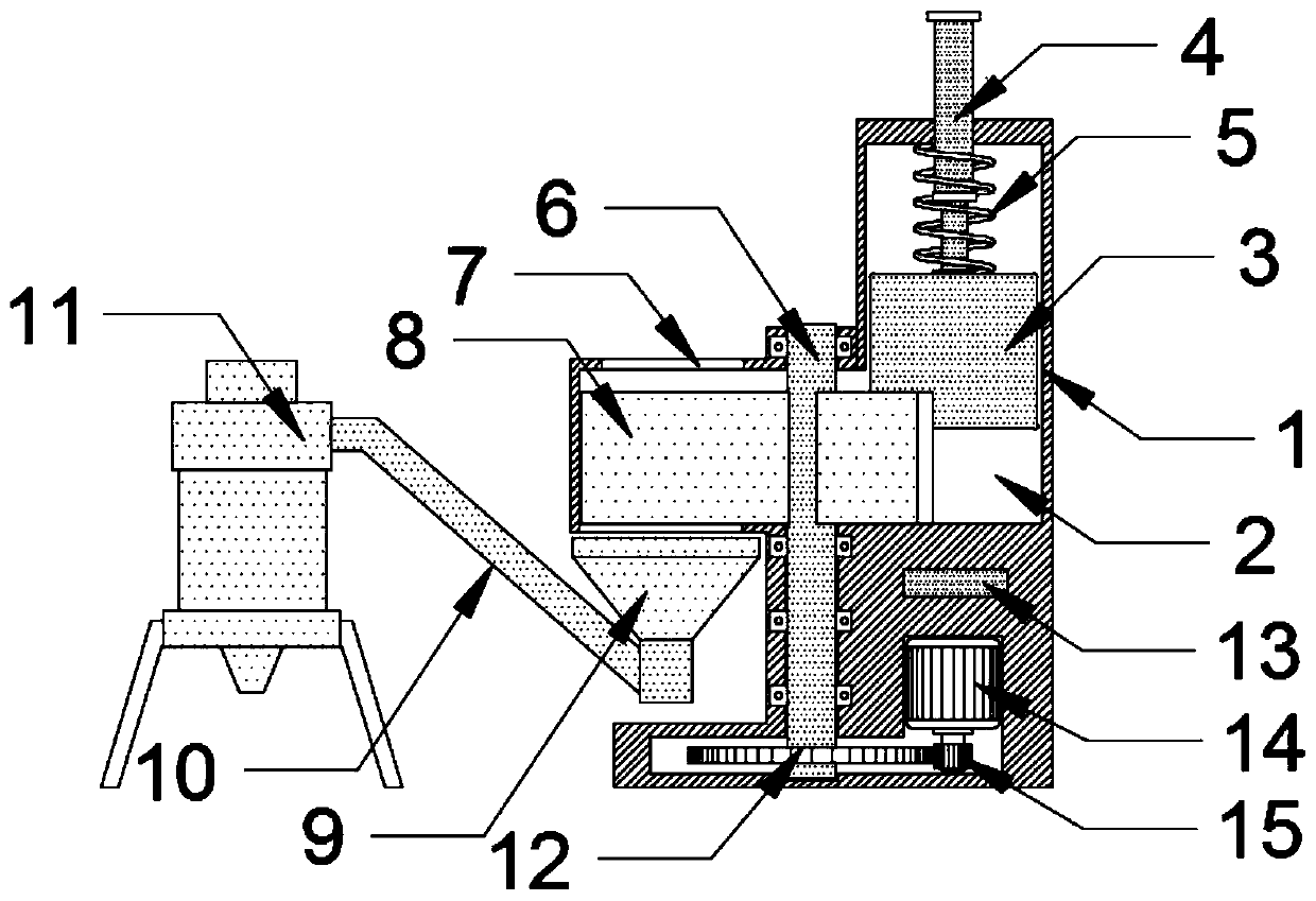
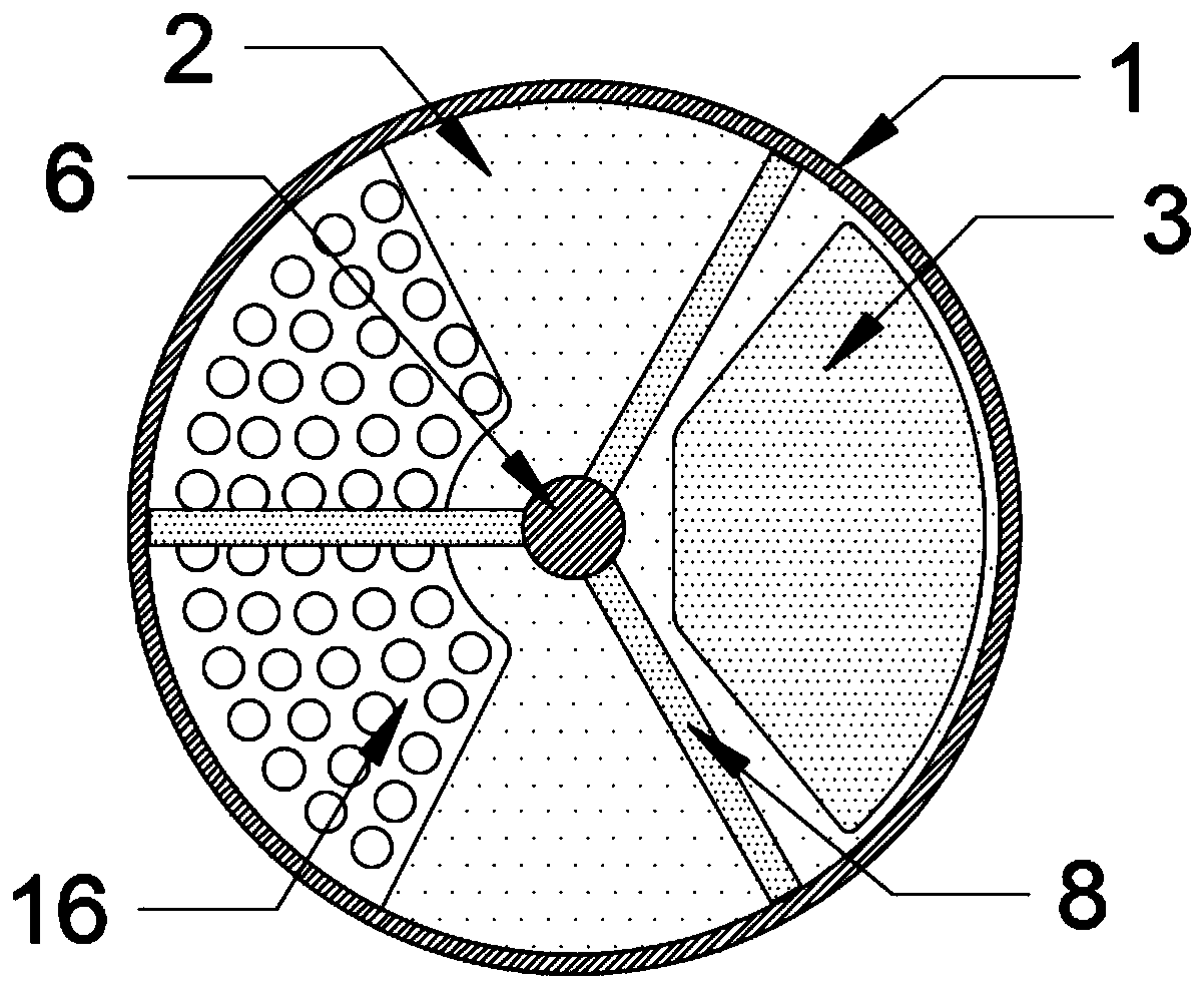
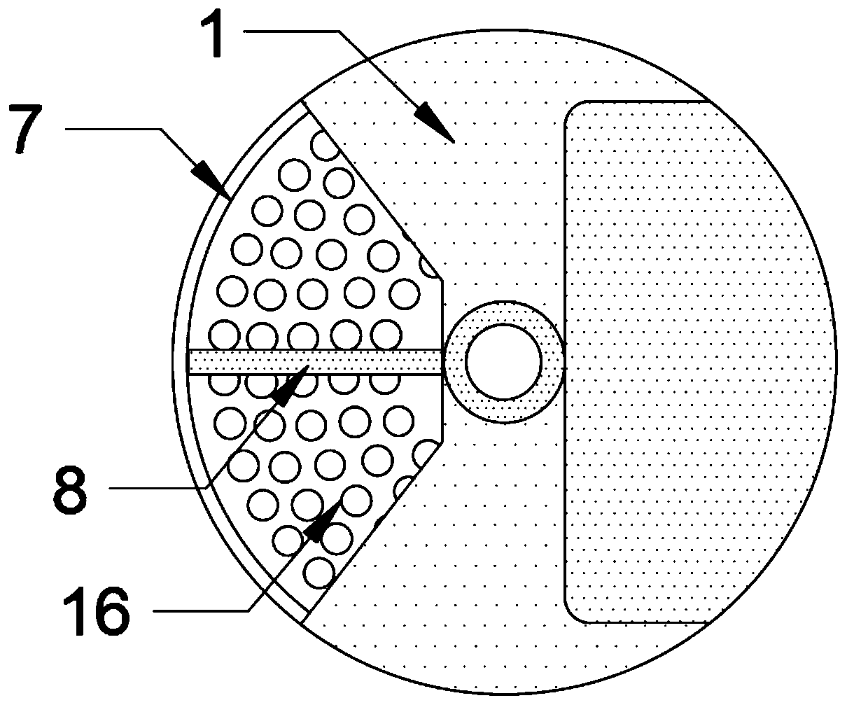
[0016] see Figure 1-3 , the present invention provides a technical solution: a shell crusher, including a body 1, a crushing bin 2, a crushing block 3, a hydraulic telescopic rod 4, a transmission shaft 6, a feed port 7, a dial 8, and an auger material guide mechanism 10. Air pulverizer 11, driven gear 12, controller 13, motor 14, driving gear 15 and orifice plate 16, the top of the body 1 is provided with a crushing bin 2, and a transmission shaft 6 is insta...
PUM
Abstract
The invention discloses a shell pulverizer. A machine body, a pulverizing bin, a crushing block, a hydraulic telescopic rod, a transmission shaft, a feeding port, stirring plates, a packing auger material guiding mechanism, an air pulverizer, a driven gear, a controller, a motor, a drive gear and a leakage hole plate are included. The pulverizing bin is arranged on the top of the machine body andinternally rotationally provided with the transmission shaft. The position, located in the pulverizing bin, of the outer wall of the transmission shaft is evenly fixedly provided with the three stirring plates. The crushing block is arranged in the pulverizing bin in a matched manner, the output end of the hydraulic telescopic rod is fixedly connected with the crushing block, and the side, away from the crushing block, of the top of the pulverizing bin is provided with the feeding port. According to the shell pulverizer, through lifting of the crushing block and in cooperation with intermittent material stirring rotation of the stirring plates, shell rough pulverizing is achieved; and through machining of the air pulverizer, high-precision pulverizing of shells is achieved, the classifiedpulverizing operation is conducted, the machining precision is improved, in addition, the machining efficiency is improved, and meanwhile the service life of equipment is prolonged.
Description
technical field [0001] The invention relates to the technical field of raw material shell processing, in particular to a shell crusher. Background technique [0002] The basic structure of the shell is mainly divided into three parts. The outermost layer is the cuticle composed of hard protein; the middle is the prismatic layer composed of calcite or aragonite crystals, which mainly provide hardness and corrosion resistance for the shell; the innermost layer is pearl The layer mainly provides hardness and toughness for shells, and is generally composed of CaCO3 minerals (inorganic phase) such as calcite or aragonite and organic matter (organic phase). Due to the high calcium content of shells, they are used as raw materials for production and need to be crushed. The air pulverizer is a relatively efficient pulverizing device, but the shell is relatively large, which is not convenient for direct air pulverization. It is not only inefficient, but also harmful to the equipment....
Claims
Application Information
Patent Timeline
Application Date:The date an application was filed.
Publication Date:The date a patent or application was officially published.
First Publication Date:The earliest publication date of a patent with the same application number.
Issue Date:Publication date of the patent grant document.
PCT Entry Date:The Entry date of PCT National Phase.
Estimated Expiry Date:The statutory expiry date of a patent right according to the Patent Law, and it is the longest term of protection that the patent right can achieve without the termination of the patent right due to other reasons(Term extension factor has been taken into account ).
Invalid Date:Actual expiry date is based on effective date or publication date of legal transaction data of invalid patent.