Drying device for electronic component dispensing

A technology for electronic components and drying devices, which is applied to the device for coating liquid on the surface, transportation and packaging, separation of dispersed particles, etc. Simple, easy to operate, easy to remove and clean

Inactive Publication Date: 2020-02-21
SUZHOU TEXIN PRECISION ELECTRONICS CO LTD
View PDF0 Cites 0 Cited by
  • Summary
  • Abstract
  • Description
  • Claims
  • Application Information

AI Technical Summary

Problems solved by technology

[0003] When the dispensing machine is dispensing, the glue is dotted on the surface of the product through the dispensing head. After the dispensing is completed, the product will be sent to the next process. However, it takes a certain amount of time for the glue to condense. If you wait for the glue to condense and set It is a waste of time to continue the follow-up processing. If you rush to follow-up processing without waiting for the glue to set and shape, it will cause the glue to fall off or bond to other parts.

Method used

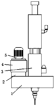
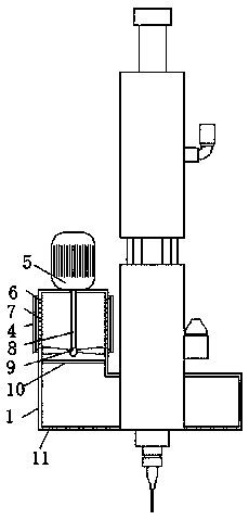
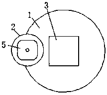

Image

  • Drying device for electronic component dispensing
  • Drying device for electronic component dispensing
  • Drying device for electronic component dispensing

Examples


Embodiment Construction

[0023] In order to make the technical means, creative features, goals and effects achieved by the present invention easy to understand, the present invention will be further described below in conjunction with specific embodiments.

[0024] In describing the present invention, it is to be understood that the terms "center", "upper", "lower", "front", "rear", "left", "right", "vertical", "horizontal", The orientations or positional relationships indicated by "top", "bottom", "inner", "outer", etc. are based on the orientations or positional relationships shown in the drawings, and are only for the convenience of describing the present invention and simplifying the description, rather than indicating or implying the It should not be construed as limiting the invention that a device or element must have a particular orientation, be constructed, and operate in a particular orientation.

[0025] In the description of the present invention, it should be noted that, unless otherwise ...


PUM


Abstract

The invention discloses a drying device for electronic component dispensing. The drying device comprises a glue dispensing head, a wind box and an air cylinder, wherein the air box fixedly adheres tothe outer wall of the bottom of the glue dispensing head, the air cylinder fixedly adhere to the middle of the left side of the wind box in a vertically penetrating manner, and a motor is in screwed connection with the middle of the top end of the air cylinder; a rotating shaft is vertically arranged in the middle of the bottom end of the motor, fan blades fixedly adhere to the bottom of the rotating shaft, and a constant-temperature heating wire mesh fixedly adheres to the bottom of an inner cavity of the air cylinder; and vent holes are formed in the top of the outer wall and the top of theinner wall of the air cylinder in a penetrating manner, and the top of the outer wall of the air cylinder is sleeved with a filter screen. According to the drying device, the motor drives the fan blades to rotate through the rotating shaft, the fan blades suck outside air from the vent holes into the inner cavity of the air cylinder through rotation, and then the fan blades blow air into the innercavity of the air box; and the air in the inner cavity of the air box is blown to the glue through blowing holes, so that the air flow rate of the surface of the glue is increased, and then the gluecan be solidified and shaped more quickly.

Description

technical field [0001] The invention relates to the technical field of dispensing and drying of dispensing machines, in particular to a drying device for dispensing glue of electronic components. Background technique [0002] Glue dispensing is a process, also known as sizing, gluing, glue pouring, glue dropping, etc. It is to smear, fill, and drop electronic glue, oil or other liquids on the product, so that the product can stick and fill. , insulation, fixation, smooth surface and so on. [0003] When the dispensing machine is dispensing, the glue is dotted on the surface of the product through the dispensing head. After the dispensing is completed, the product will be sent to the next process. However, it takes a certain amount of time for the glue to condense. If you wait for the glue to condense and set It is a waste of time to continue the follow-up processing. If you rush to follow-up processing without waiting for the glue to set and set, it will cause the glue to f...

Claims


Application Information

Patent Timeline
Patent Type & Authority Applications(China)
IPC IPC(8): B05D3/04B01D46/00B01D46/24
CPCB05D3/0413B01D46/2411B01D46/88
Inventor 方国章
Owner SUZHOU TEXIN PRECISION ELECTRONICS CO LTD
Why Eureka
Try Eureka