
Automatic garbage recovery device and recovery method thereof

A recycling device and garbage technology, which is applied in the direction of grain processing, solid waste removal, etc., can solve problems such as inability to clean, slag inclusions and large particles of debris in products, cumbersome operations, etc.

Inactive Publication Date: 2020-02-21
苏州德君环卫服务有限公司
View PDF9 Cites 3 Cited by
  • Summary
  • Abstract
  • Description
  • Claims
  • Application Information

AI Technical Summary

Problems solved by technology

[0005] The purpose of the present invention is to provide an automatic garbage recovery device and its recovery method, to solve the problem that the existing garbage recovery device cannot process the toxic substances contained in the garbage, and the toxic substances in the garbage cannot be eliminated only by crushing. Substances, resulting in processed products containing toxic substances, endangering the health of users; the recycled garbage cannot be completely crushed by a simple crushing device, and it is easy to cause slag inclusions and large particles of debris in the product, difficult processing, and poor product quality; The crushed garbage falls into the storage box. When the existing storage box stores the crushed garbage, it is easy to cause the blockage of the discharge port. Workers need to use sticks to stir the garbage at the discharge port, which leads to the purpose of dredging and cumbersome operation. , the workload is relatively large; the storage box of the existing garbage collection device is a closed structure, and the inside of the storage box cannot be cleaned after use, resulting in long-term products sticking to the inner wall of the storage box, making different types of garbage recycling When it is mixed, it can only meet the same type of garbage collection work, and it is inconvenient to use

Method used


Image

  • Automatic garbage recovery device and recovery method thereof
  • Automatic garbage recovery device and recovery method thereof
  • Automatic garbage recovery device and recovery method thereof

Examples


Embodiment Construction

[0034] The technical solutions of the present invention will be clearly and completely described below in conjunction with the embodiments. Apparently, the described embodiments are only some of the embodiments of the present invention, not all of them. Based on the embodiments of the present invention, all other embodiments obtained by persons of ordinary skill in the art without creative efforts fall within the protection scope of the present invention.

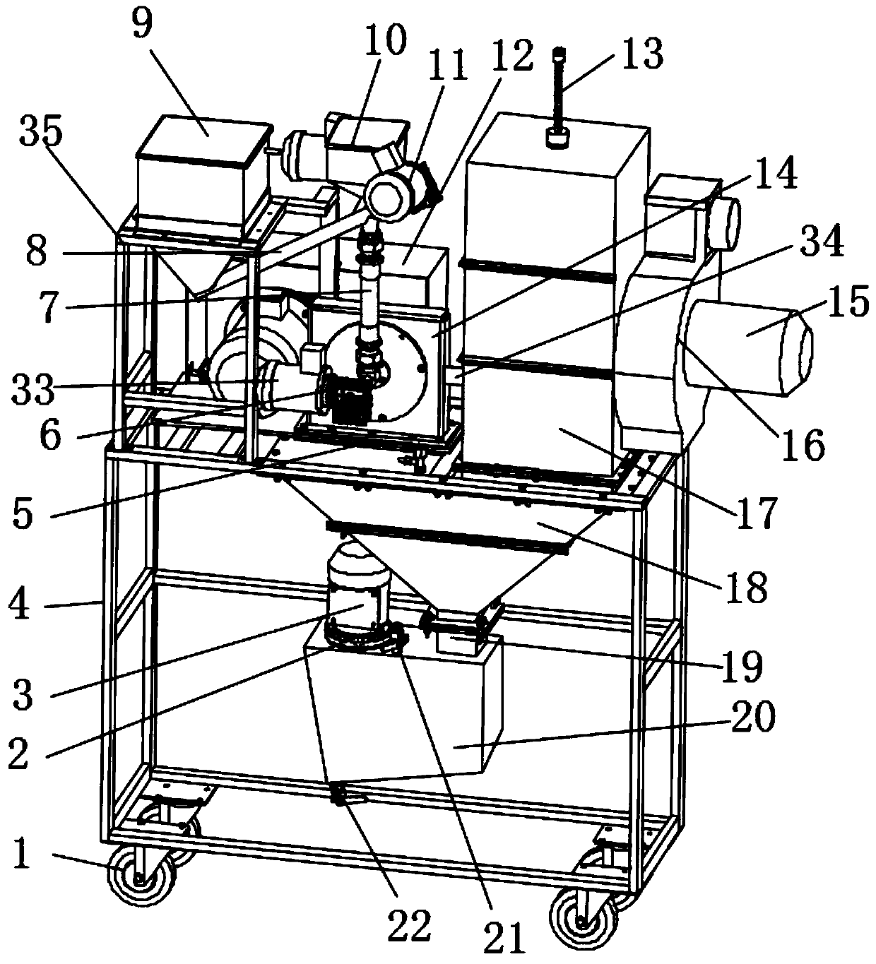
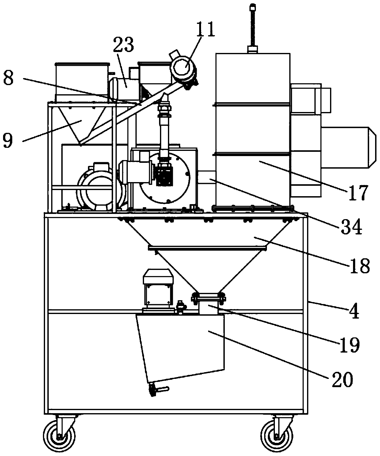
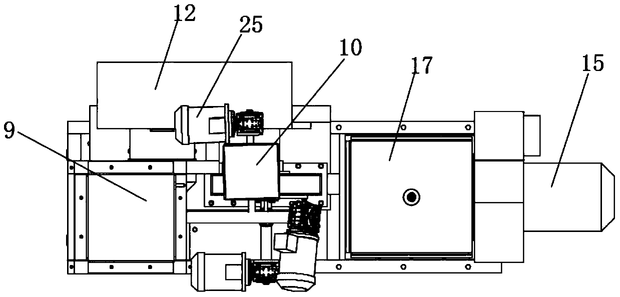
[0035] Such as Figure 1-7 As shown, a kind of automatic garbage recovery device comprises base 4, feeding box 9 and crushing box 14, and the top end of described base 4 is fixedly provided with mounting frame 35, and the top of mounting frame 35 is provided with feeding box 9, upper The bottom of the hopper 9 is provided with a feeding pipe 8, and the top of the base 4 on the mounting frame 35 side is provided with a cover plate 5, and the top of the cover plate 5 is fixedly provided with a support column 24, and the top o...


PUM


Abstract

The invention discloses an automatic garbage recovery device. The automatic garbage recovery device comprises a base, a feed box and a crushing box. A mounting rack is fixedly arranged at one end of the top of the base. The feed box is arranged on the top of the mounting rack. The bottom of the feed box is provided with a feed pipe. A cover plate is arranged in the position, on one side of the mounting rack, of the top of the base. The top of the cover plate is fixedly provided with supporting columns. Crushed garbage is fed into a collection box from the bottom of the crushing box and goes into a storage box through a transition pipe. The bottom surface of the storage box is an inclined plane, and a discharge port is arranged at the bottom of the inclined plane, so that the crushed garbage slides to the discharge port under the action of gravity and is discharged from the discharge port. Meanwhile, the output end of an unchoking motor drives an unchoking shaft to rotate, and unchokingblades on the unchoking shaft rotate to stir the crushed garbage to move, so that the crushed garbage can be discharged from the discharge port. The automatic garbage recovery device achieves the crushed garbage unchoking effect to protect materials against accumulation and blockage.

Description

technical field [0001] The invention relates to the field of garbage recycling equipment, in particular to an automatic garbage recycling device and a recycling method thereof. Background technique [0002] Garbage classification refers to the classified storage, classified placement and classified transportation of garbage according to certain regulations or standards, so as to transform them into public resources. The current garbage recycling device only performs the next step of processing after the initial crushing by the shredder. The garbage that is not completely crushed is likely to cause slag inclusions and large particles of debris in the product, resulting in processing difficulties. [0003] The Chinese patent with the publication number CN105398714B discloses a garbage recovery device including: a support frame, a bucket body, a cigarette butt recovery component, a switch and a connecting rod component. The supporting frame includes a base, a supporting frame ...

Claims


Application Information

Patent Timeline
IPC IPC(8): B09B3/00B09B5/00B02C19/18B02C21/02A62D3/30
CPCA62D3/30B02C19/186B02C21/02B02C2201/06B09B3/00B09B5/00
Inventor 张德君
Owner 苏州德君环卫服务有限公司
Learn More