Mold core with ultrasonic vibration device

A vibrating device and ultrasonic technology, applied in cores, casting molding equipment, casting molds, etc., can solve problems such as poor exhaust, reduced production capacity and pass rate, pinhole residue, etc., to improve exhaust speed and exhaust The effect of speed, speed up filling and forming, and refinement of crystal grains

Pending Publication Date: 2020-02-21
WUXI LIHU PRESSURIZE TECH CO LTD
View PDF0 Cites 1 Cited by
  • Summary
  • Abstract
  • Description
  • Claims
  • Application Information

AI Technical Summary

Problems solved by technology

[0002] In order to keep up with the pace of energy saving and emission reduction, the popularity of superchargers in fuel vehicles has been developing and is highly competitive; the aluminum alloy compressor casing at one end of the supercharger is produced in the production process of metal mold gravity casting And it is easy to produce pores, which seriously affects the product qualification rate; the traditional method of degassing the lower mold today still only relies on setting an exhaust plug on the top of the core of the lower mold to exhaust, and its position is just below the gate, which is often compared Blockage occurs when the high-temperature aluminum liquid is poured, resulting in poor exhaust and air bubbles and pinholes remaining in the product, and it is difficult for the operator to detect it at the time. After the detection is found, the only way to do it is to remove the mold, remove the mold, and replace the exhaust plug. production, resulting in increased mold maintenance workload, decreased production capacity and pass rate; in this industry, although ultrasonic vibration devices are used to degas the aluminum liquid or install it on the upper mold and retract it after treatment, its degassing effect Small, the effect on crystallization is not obvious, and the structure is complex

Method used


Image

  • Mold core with ultrasonic vibration device
  • Mold core with ultrasonic vibration device
  • Mold core with ultrasonic vibration device

Examples


Embodiment Construction

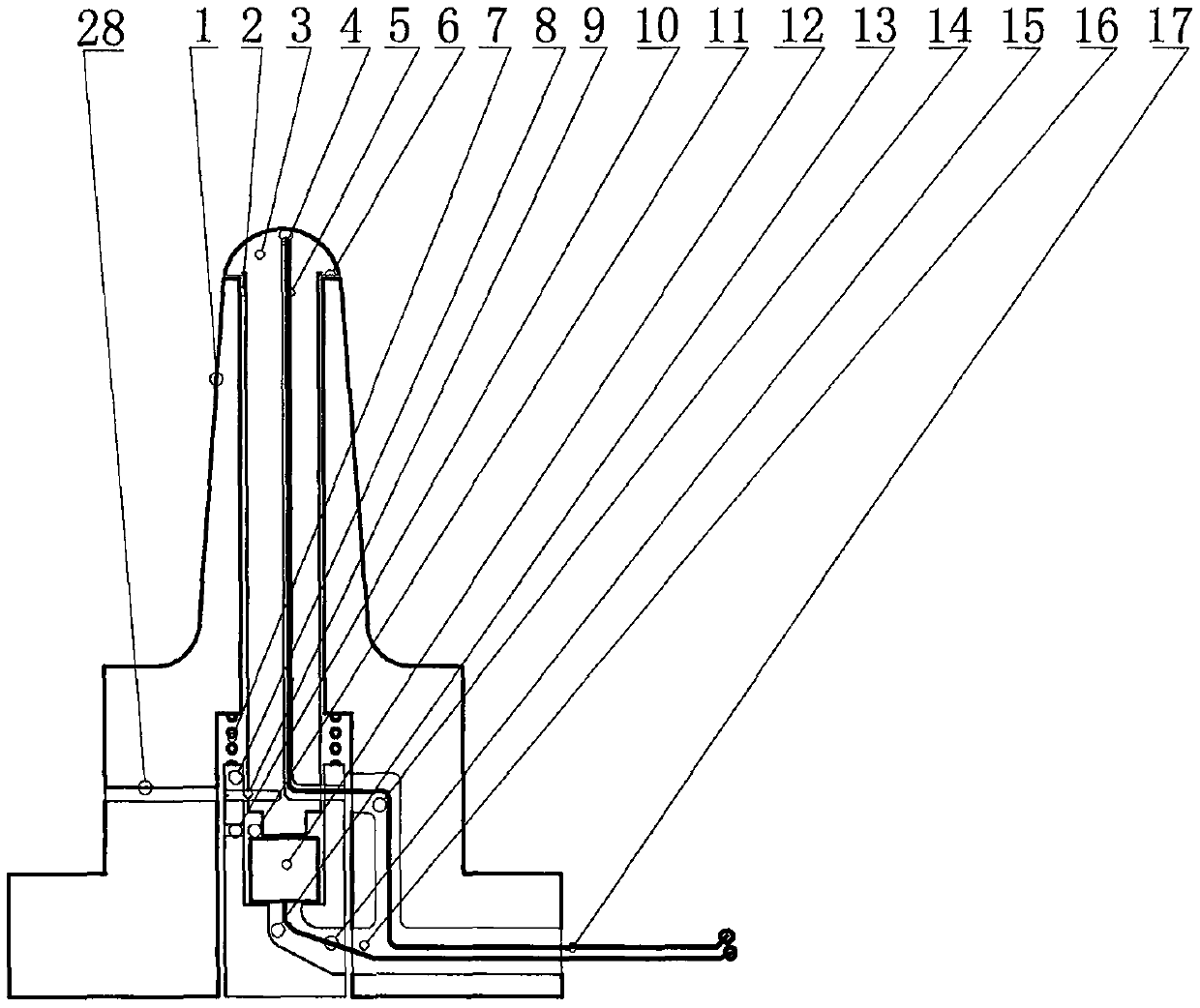
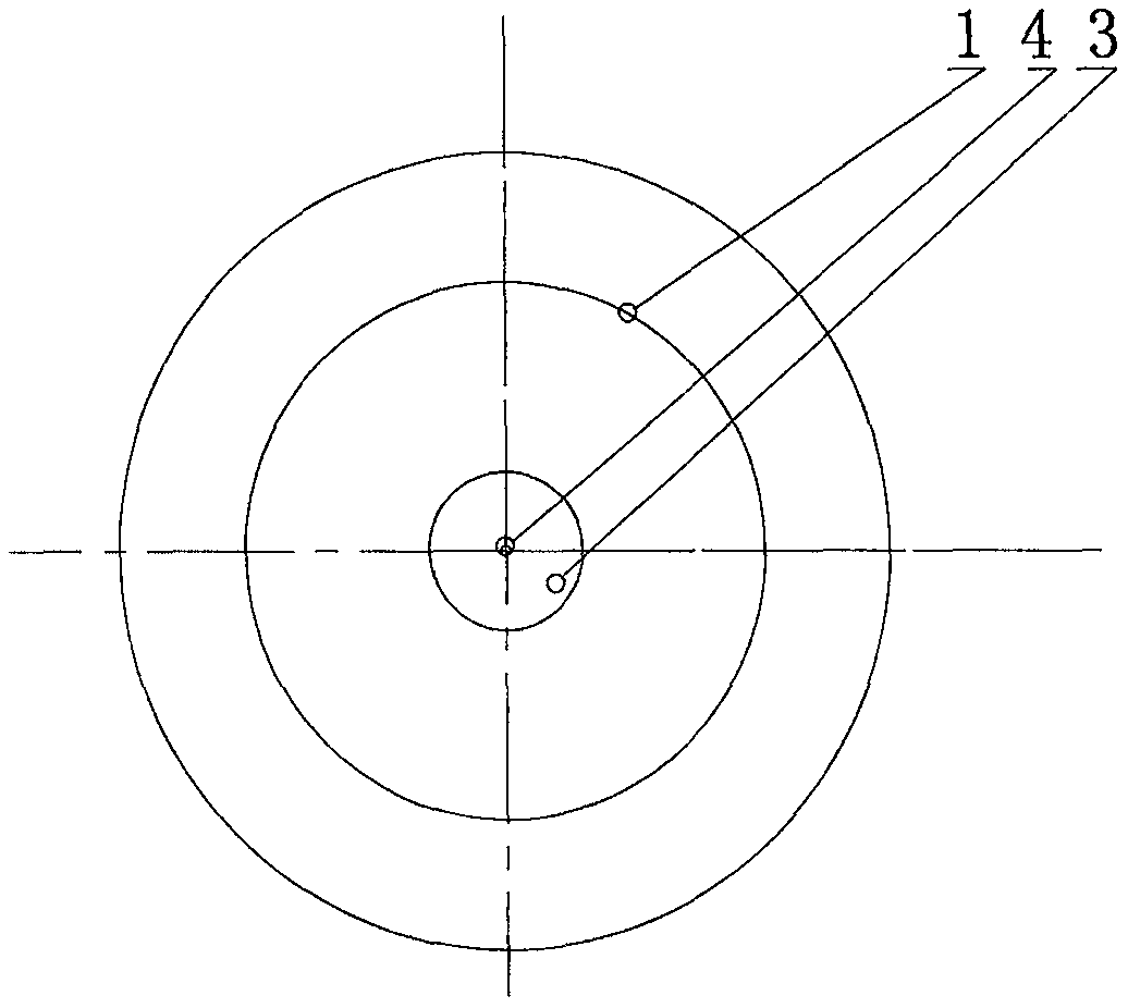
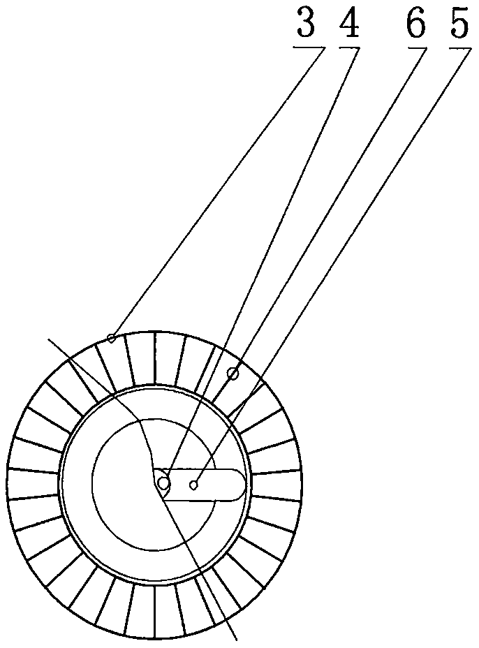
[0031] The specific implementation manners in this application will be further described below in conjunction with the accompanying drawings.

[0032] In the figure, it includes the mold core (1), the mold core hole (2), the mold core head (3), the thermocouple (4), the hole for the temperature measuring line (5), the embossed exhaust channel (6), the compression spring (7), transducer chamber (8), connecting pin (9), cooling outlet duct (10), transducer cavity (11), transducer (12), wire inlet duct (13), cooling duct (14), transducer wire (15), composite channel (16), temperature measuring line (17), compressor shell product (18), upper mold (19), mold heating pipe (20), ejector rod (21 ), lower mold composite channel (22), lower mold (23), compressor casing product runner (24), sprue cup (25), gate (26), composite channel interface (27), connecting pin installation hole (28), the top plate (29) etc. that push rod and back-moving spring are housed.

[0033] figure 1 Shown ...


PUM


Abstract

The invention discloses a mold core with an ultrasonic vibration device. The mold core is characterized in that the mold core comprises a mold core mechanism, an exhaust mechanism, a transducer cooling mechanism and a channel mechanism; according to the mold core mechanism, the mold core is provided with a mold core hole, a mold core head and a mold core rod are arranged in the mold core hole, hole channels for measuring temperature wire are arranged in the mold core head and the mold core rod, thermocouples for measuring temperature is arranged in the top end of the hole channel, the exhaustmechanism is arranged on the opposite side of the mold core head and on the outer surface of the mold core rod, the transducer cooling mechanism is arranged on the lower part of the mold core rod; andan ultrasonic transducer is arranged on the lower end of the mold core rod. According to the mold core with the ultrasonic vibration device, the ultrasonic vibration device fixed in the lower mold ofa metal mold is adopted so that aluminum liquid being injected is subjected ultrasonic vibration, so that the filling and forming are accelerated, the orderly exhaust speed is accelerated at the sametime, the forming quality of products is improved, the mold core is cooled automatically and rapidly, the air cooling process of manual operation is omitted, and the product quality and output are improved.

Description

technical field [0001] The application relates to a mold for gravity casting of a metal mold in the field of aluminum alloy casting, in particular to a mold core with an ultrasonic vibration device used in the lower mold of the metal mold. Background technique [0002] In order to keep up with the pace of energy saving and emission reduction, the popularity of superchargers in fuel vehicles has been developing and is highly competitive; the aluminum alloy compressor casing at one end of the supercharger is produced in the production process of metal mold gravity casting And it is easy to produce pores, which seriously affects the product qualification rate; the traditional method of degassing the lower mold today still only relies on setting an exhaust plug on the top of the core of the lower mold to exhaust, and its position is just below the gate, which is often compared Blockage occurs when the high-temperature aluminum liquid is poured, resulting in poor exhaust and air ...

Claims


Application Information

Patent Timeline
Patent Type & Authority Applications(China)
IPC IPC(8): B22C9/10B22D27/08B22D27/04
CPCB22C9/10B22D27/04B22D27/08
Inventor 邵宏
Owner WUXI LIHU PRESSURIZE TECH CO LTD
Why Eureka
Try Eureka