A chip collection device at the bottom of a turning machine tool

A collection device, turning machine tool technology, applied in the direction of metal processing machinery parts, metal processing equipment, maintenance and safety accessories, etc., can solve the problems of high cost, occupied space, scattered iron wires, etc., to achieve convenient disassembly and subsequent processing, and save processing The effect of space and convenient recycling

Active Publication Date: 2021-05-04
NANJING CHENGUANG GRP +1
View PDF8 Cites 0 Cited by
  • Summary
  • Abstract
  • Description
  • Claims
  • Application Information

AI Technical Summary

Problems solved by technology

[0002] At present, with the development of society, the field of mechanical processing has been vigorously developed, but the traditional turning machine tools still have a large number of irregular scattering of iron wires and iron filings in the collection box after turning. It is usually necessary to clean the iron wire and scrap iron in the collection box, but the iron wire is very sharp and can easily scratch the skin of the staff. At present, we collect the fallen iron scrap and put it in a centralized collection place, but because the irregular arrangement of the processed iron wires takes up a lot of space, and the staff cannot compress them by hand, and the use of a compressor will cause the problem of high cost, so it is necessary to invent a kind of chip at the bottom of the turning machine tool collection device

Method used


Image

  • A chip collection device at the bottom of a turning machine tool
  • A chip collection device at the bottom of a turning machine tool
  • A chip collection device at the bottom of a turning machine tool

Examples


Embodiment Construction

[0017] All features disclosed in this specification, or steps in all methods or processes disclosed, can be combined in any way, except for mutually exclusive features and steps.

[0018] Any feature disclosed in this specification (including any appended claims, abstract and drawings), unless expressly stated otherwise, may be replaced by alternative features which are equivalent or serve a similar purpose. That is, unless expressly stated otherwise, each feature is one example only of a series of equivalent or similar features.

[0019] Combine below Figure 1-3 The present invention is described in detail, and for convenience of description, the orientations mentioned below are now stipulated as follows: figure 1 The up, down, left, right, front and back directions of the projection relationship itself are the same.

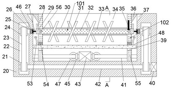
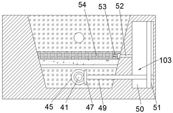
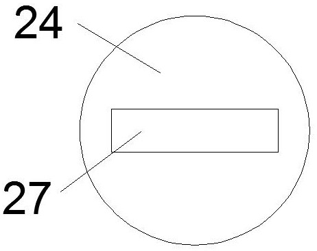
[0020] see Figure 1-4 , an embodiment provided by the present invention: a chip collection device at the bottom of a turning machine tool, including a bod...


PUM


Abstract

The invention discloses a debris collection device at the bottom of a turning machine tool, which comprises a machine body. A collection chamber is arranged in the body. The left and right sides of the collection chamber are symmetrically provided with pulley chambers, and the rear side of the collection chamber is provided with water storage. cavity, and there is a communication cavity symmetrically connected between the collection cavity and the water storage cavity. The motor shaft rotates, thereby driving the two extrusion plates close to each other, thereby pushing the paper tube, the The iron filings and iron wire on the paper rod are compressed, and the paper tube and the paper rod are compressed at the same time. The present invention collects the iron wire and scrap iron through the collection device, and collects the iron wire and scrap iron, avoiding the The traditional collection box is directly scattered on the lower side, but the invention uses a compression device to compress the iron wire into a cake shape, which not only facilitates the disassembly and subsequent processing of the staff.

Description

technical field [0001] The invention relates to the field of turning, in particular to a debris collection device at the bottom of a turning machine tool. Background technique [0002] At present, with the development of society, the field of mechanical processing has been vigorously developed, but the traditional turning machine tools still have a large number of irregular scattering of iron wires and iron filings in the collection box after turning. It is usually necessary to clean the iron wire and scrap iron in the collection box, but the iron wire is very sharp and can easily scratch the skin of the staff. At present, we collect the fallen iron scrap and put it in a centralized collection place, but because the irregular arrangement of the processed iron wires takes up a lot of space, and the staff cannot compress them by hand, and the use of a compressor will cause the problem of high cost, so it is necessary to invent a kind of chip at the bottom of the turning machin...

Claims


Application Information

Patent Timeline
Patent Type & Authority Patents(China)
IPC IPC(8): B23Q11/00
CPCB23Q11/0064B23Q11/0067
Inventor 陈媚
Owner NANJING CHENGUANG GRP
Why Eureka
Try Eureka