
Six-degree-of-freedom hydraulic mechanical arm

A technology of hydraulic machinery and degrees of freedom, used in manipulators, claw arms, manufacturing tools, etc., can solve the problems of less freedom of manipulators, single manipulators, high cost, low protection level requirements, high-precision positioning, and compact structure. Effect

Active Publication Date: 2020-02-21
NANJING UNIV OF SCI & TECH
View PDF5 Cites 5 Cited by
  • Summary
  • Abstract
  • Description
  • Claims
  • Application Information

AI Technical Summary

Problems solved by technology

The robotic arm is the earliest automated industrial robot that can simulate certain movements of the human arm to grab and carry objects with a fixed program. If it is necessary to ensure the precise placement of objects, it cannot be done by a single robotic arm, resulting in the need for more auxiliary devices. At present, a single industrial manipulator has few degrees of freedom and cannot complete transmissions that require higher precision. Therefore, improving the degree of freedom of the joints of the manipulator is an urgent problem to be solved.
Moreover, at present, most of the mechanical arms in the industry are driven by electricity, which has the disadvantages of high cost and high maintenance requirements.

Method used


Image

  • Six-degree-of-freedom hydraulic mechanical arm
  • Six-degree-of-freedom hydraulic mechanical arm
  • Six-degree-of-freedom hydraulic mechanical arm

Examples


Embodiment Construction

[0014] The present invention will be described in further detail below in conjunction with the accompanying drawings.

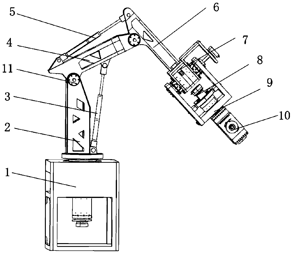
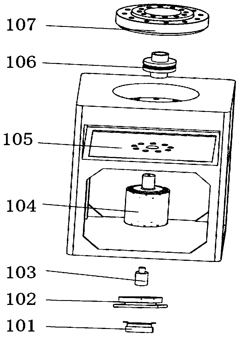
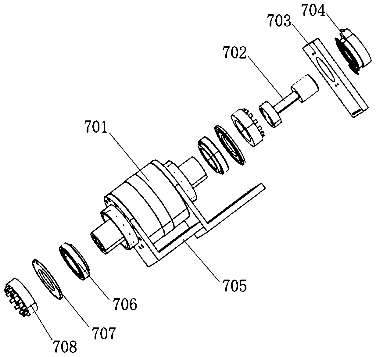
[0015] combine Figure 1 to Figure 6 , a six-degree-of-freedom hydraulic mechanical arm according to the present invention includes a base rotary joint 1, a large arm 2, a first telescopic joint 3, a first mechanical arm 4, a second telescopic joint 5, a second mechanical arm 6, and a swing Joint 7, roll joint 8, roll support 9, pitch joint 10 and two bearing assemblies 11. A total of six degrees of freedom are set, including a large arm rotation degree of freedom, two telescopic degrees of freedom, a swing degree of freedom, a rolling degree of freedom and a pitching degree of freedom at the wrist of the mechanical arm. The base rotary joint 1 can realize 270-degree reciprocating rotary motion. One end of the big arm 2 is fixed on the top surface of the base rotary joint 1, and the other end is rotationally connected with one end of the first mechanical arm...


PUM


Abstract

The invention discloses a six-degree-of-freedom hydraulic mechanical arm, and belongs to the technical field of mechanical equipment. The six-degree-of-freedom hydraulic mechanical arm comprises a base rotary joint, a big arm, a first telescopic joint, a first mechanical arm, a second telescopic joint, a second mechanical arm, a horizontal swing joint, a rolling swing joint, a rolling swing support, a pitching joint and two bearing assemblies; one end of the big arm is fixed to the top surface of the base rotary joint, and the other end of the big arm is rotationally connected with one end ofthe first mechanical arm through the bearing assemblies; the other end of the first mechanical arm is rotationally connected with one end of the second mechanical arm, and the other end of the secondmechanical arm is fixedly connected with the horizontal swing joint; the rolling swing support is rotationally connected with the horizontal swing joint, the rolling swing joint is arranged on the inner side of the rolling swing support, and the pitching joint is rotationally connected with the rolling swing support; the two ends of the first telescopic joint are rotationally connected with the big arm and the first mechanical arm correspondingly, and the two ends of a second telescopic joint are rotationally connected with the first mechanical arm and the second mechanical arm correspondingly. According to the six-degree-of-freedom hydraulic mechanical arm, hydraulic driving is adopted, so that the working angle can be accurately adjusted.

Description

technical field [0001] The invention belongs to the technical field of mechanical equipment, in particular to a six-degree-of-freedom hydraulic mechanical arm. Background technique [0002] In the modern machinery industry, automated mechanical equipment has replaced human labor in large quantities, and the work efficiency has been greatly improved. At the same time, it can operate in harsh environments to ensure personal safety. The robotic arm is the earliest automated industrial robot that can simulate certain movements of the human arm to grab and carry objects with a fixed program. If it is necessary to ensure the precise placement of objects, it cannot be done by a single robotic arm, resulting in the need for more auxiliary devices. At present, a single industrial manipulator has few degrees of freedom and cannot complete transmissions that require higher precision. Therefore, improving the degree of freedom of the joints of the manipulator is an urgent problem to be ...

Claims


Application Information

Patent Timeline
Patent Type & Authority Applications(China)
IPC IPC(8): B25J17/02B25J18/00
CPCB25J17/02B25J18/00
Inventor 姚建勇赵先亮邓文翔王子龙尤立宇朱威霖周瑾米君杰
Owner NANJING UNIV OF SCI & TECH
Learn More