
Automatic charging pad

An electric pad and automatic technology, applied in the field of automatic power supply pad, can solve the problems of serious heating of power receiving equipment and charging device, battery life charging obstacle, waste of energy, etc., and achieve anti-oxidation environment tolerance, usability and reliability High, the effect of improving the ability of reliable contact

Pending Publication Date: 2020-02-21
星逻人工智能技术(上海)有限公司
View PDF0 Cites 0 Cited by
  • Summary
  • Abstract
  • Description
  • Claims
  • Application Information

AI Technical Summary

Problems solved by technology

Non-contact online charging devices (such as wireless charging devices) that do not require high positioning requirements and do not require conductive contact are generally inefficient. obstacle

Method used


Image

  • Automatic charging pad
  • Automatic charging pad
  • Automatic charging pad

Examples


Embodiment Construction

[0039] A detailed description of an automatic power supply pad provided by the present invention will be given below in conjunction with the accompanying drawings. This embodiment is implemented on the premise of the technical solution of the present invention, and a detailed implementation method and specific operation process are given. However, this embodiment The protection scope of the invention is not limited to the following embodiments, and those skilled in the art can modify and embellish it within the scope of not changing the spirit and content of the invention.

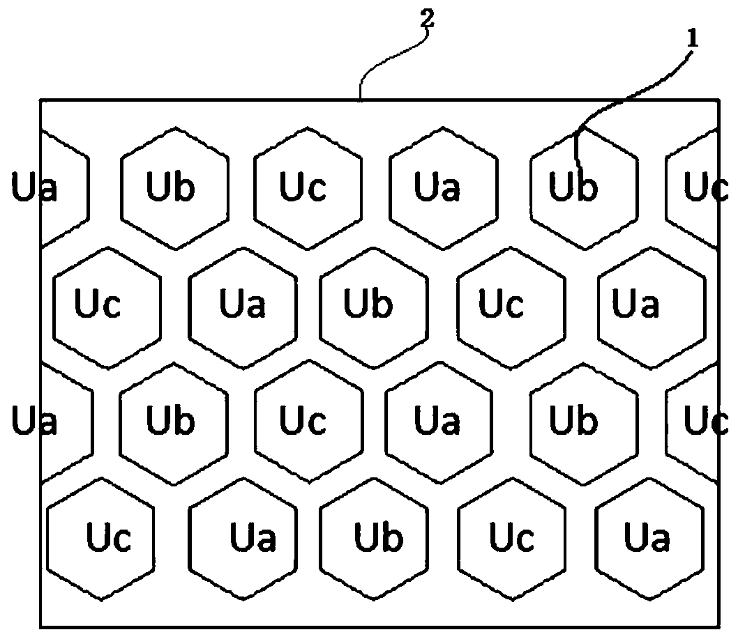
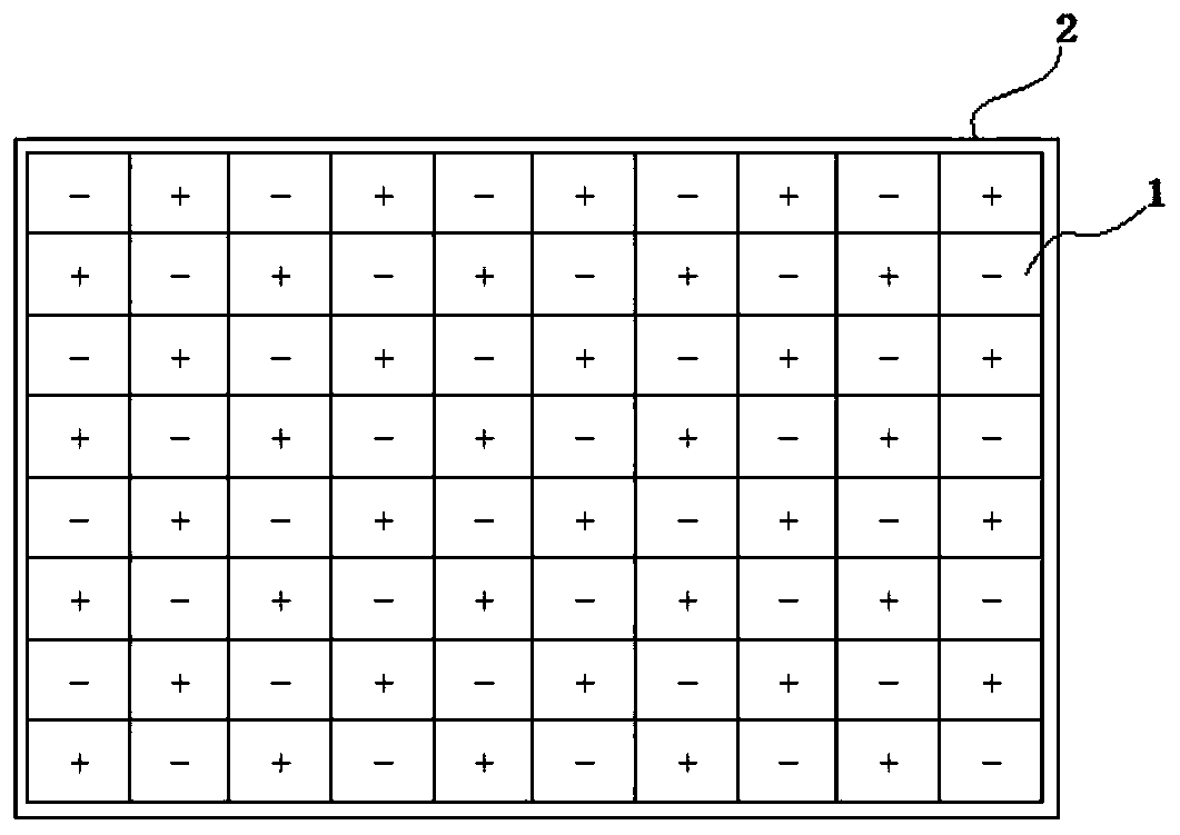
[0040] The automatic power transmitting pad disclosed by the invention is a contact type power transmitting device which can conveniently and effectively supply power and charge the power receiving device.

[0041] Please refer to figure 1 and figure 2 , an automatic power supply pad, including a base pad 2, an electrode control module (not shown in the figure) and a plurality of honeycomb or matrix elec...


PUM


Abstract

The invention discloses an automatic charging pad. The pad comprises a base pad body, an electrode control module and at least two electrodes, wherein the electrodes are arranged on the surface of thebase pad body, and any two adjacent electrodes are mutually non-conductive; the input end of the electrode control module is connected with a power supply, and the output end of the electrode controlmodule is connected with each electrode; and when charging is carried out, a to-be-charged device contacts the surface of the base pad body, so that different to-be-charged contacts of the to-be-charged device and at least two electrodes are conductive, and the electrode control module exerts a voltage between the electrodes in contact with the to-be-charged contacts to form a current loop for charging the to-be-charged device. A contact type charging device is provided and is capable of conveniently and effectively supplying power to and charging mobile equipment.

Description

technical field [0001] The invention relates to the technical field of power supply and charging, in particular to an automatic power supply pad. Background technique [0002] In recent years, mobile devices such as robots, electric vehicles, and unmanned aerial vehicles have been widely used. Movable equipment is mainly powered by cables or energy storage components such as rechargeable batteries and supercapacitors: when using cables for power supply, the position and moving distance of movable equipment will be limited; when using rechargeable batteries, supercapacitors and other energy storage components for power supply, When the electric energy stored in the energy storage element is exhausted, the mobile device needs to replenish electric energy to continue working. [0003] Traditional charging methods are divided into two types: offline charging and online charging: offline charging usually requires manual removal of the energy storage components of the mobile devi...

Claims


Application Information

Patent Timeline
Patent Type & Authority Applications(China)
IPC IPC(8): B60L53/14
CPCB60L53/14Y02T10/70Y02T10/7072Y02T90/14Y02T90/16
Inventor 郝利静王海滨钱茂冬
Owner 星逻人工智能技术(上海)有限公司
Learn More