High-efficiency automatic feeding equipment

A feeding equipment and high-efficiency technology, applied in the field of high-efficiency automatic feeding equipment, can solve the problems of low discharge rate, surface material cleaning that cannot drive the shaft, stuck, etc., to achieve the effect of improving production efficiency

Inactive Publication Date: 2020-02-21
苏州吉玛自动化科技有限公司
View PDF0 Cites 1 Cited by
  • Summary
  • Abstract
  • Description
  • Claims
  • Application Information

AI Technical Summary

Problems solved by technology

[0003] When the traditional feeding equipment is in use, it cannot apply stirring force to the material, so that the practical effect of the equipment is not good, and the output rate is low. At the same time, the surface material of the drive shaft cannot be cleaned, and it is easy to cause jams due to blockage during the transmission process. Inconvenience to the use of feeding equipment

Method used


Image

  • High-efficiency automatic feeding equipment
  • High-efficiency automatic feeding equipment
  • High-efficiency automatic feeding equipment

Examples


Embodiment 1

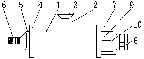
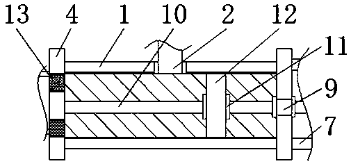
[0023] refer to Figure 1-2 , a high-efficiency automatic feeding equipment, including a barrel 1, the barrel 1 is installed horizontally, and the middle position of the upper surface of the barrel 1 is vertically welded with a feed pipe 2, and the two side walls of the barrel 1 are fixedly installed with a barrel Cover 4, the two groups of cylinder covers 4 are welded with a hopper 5 and a fixing frame 7 on the side of the outer wall that is far away from each other. A motor 8 is installed in a fixed position, and a sealing sleeve 9 is welded between the middle positions of the outer walls on both sides of a group of cylinder covers 4, and the middle position of the side wall of the motor 8 is vertically movably connected with a rotating shaft 10 through a fixed frame 7, and the outer parts of the rotating shaft 10 A screw sleeve 11 is arranged on the surface, and an annular disc 12 is fixedly sleeved on the outer surface of the screw sleeve 11 .

[0024] Wherein, the lower ...

Embodiment 2

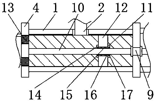
[0031] refer to figure 1 image 3 , a high-efficiency automatic feeding equipment, including a barrel 1, the barrel 1 is installed horizontally, and the middle position of the upper surface of the barrel 1 is vertically welded with a feed pipe 2, and the two side walls of the barrel 1 are fixedly installed with a barrel Cover 4, the two groups of cylinder covers 4 are welded with a hopper 5 and a fixing frame 7 on the side of the outer wall that is far away from each other. A motor 8 is installed in a fixed position, and a sealing sleeve 9 is welded between the middle positions of the outer walls on both sides of a group of cylinder covers 4, and the middle position of the side wall of the motor 8 is vertically movably connected with a rotating shaft 10 through a fixed frame 7, and the outer parts of the rotating shaft 10 A screw sleeve 11 is arranged on the surface, and an annular disc 12 is fixedly sleeved on the outer surface of the screw sleeve 11 .

[0032] Wherein, the...


PUM


Abstract

The invention discloses high-efficiency automatic feeding equipment which comprises a charging barrel. The charging barrel is transversely installed. A feeding pipe is perpendicularly welded to the middle of the upper surface of the charging barrel. The two side walls of the charging barrel are each fixedly provided with a barrel cover. A discharging hopper and a fixing frame are welded to the outer walls of the sides, away from each other, of the two barrel covers respectively, the longitudinal section of the fixing frame is in a concave shape, and a motor is fixedly installed at the middle of the outer wall of the side, away from the charging barrel, of the fixing frame. A sealing sleeve is welded between the middles of the outer walls at the two sides of one barrel cover, and a rotatingshaft is perpendicularly and movably connected to the middle of one side wall of the motor through the fixing frame. A nut is arranged on the outer surface of the rotating shaft, and the outer surface of the nut is fixedly sleeved with an annular disc. According to the high-efficiency automatic feeding equipment, the feeding equipment can apply stirring force to materials so as to enhance the practical effect, the discharging rate is increased, and meanwhile materials on the surface of a driving shaft can be cleaned away so as to ensure the smooth effect of conveying.

Description

technical field [0001] The invention relates to the technical field of feeding, in particular to a high-efficiency automatic feeding device. Background technique [0002] Feeding equipment provides material conveying space to realize automatic feeding of processing equipment. Compared with manual feeding mode, it saves time and effort to improve production efficiency. The use of feeding equipment on production lines is more common. [0003] When the traditional feeding equipment is in use, it cannot apply stirring force to the material, so that the practical effect of the equipment is not good, and the output rate is low. At the same time, the surface material of the drive shaft cannot be cleaned, and it is easy to cause jams due to blockage during the transmission process. The situation brings inconvenience to the use of feeding equipment. Contents of the invention [0004] The object of the present invention is to propose a high-efficiency automatic feeding device in or...

Claims


Application Information

Patent Timeline
Patent Type & Authority Applications(China)
IPC IPC(8): B65G65/40B65G69/10B08B1/02
CPCB08B1/002B08B1/02B65G65/40B65G69/10
Inventor 饶智超
Owner 苏州吉玛自动化科技有限公司
Why Eureka
Try Eureka