
Cable processing winding machine

A winding machine and cable technology, which is applied in the direction of conveying filamentous materials, thin material processing, transportation and packaging, etc., can solve the problems of inconvenient use, messy winding, and inability to guide the cable, so as to improve the winding power and prevent Knotted, stability-enhancing effect

Inactive Publication Date: 2020-02-21
惠州市鑫弘诚电子科技有限公司
View PDF7 Cites 7 Cited by
  • Summary
  • Abstract
  • Description
  • Claims
  • Application Information

AI Technical Summary

Problems solved by technology

However, the above-mentioned patents cannot guide the cable during the winding process, and it is easy to cause messy winding during the actual winding process, which will cause inconvenience to subsequent use.

Method used

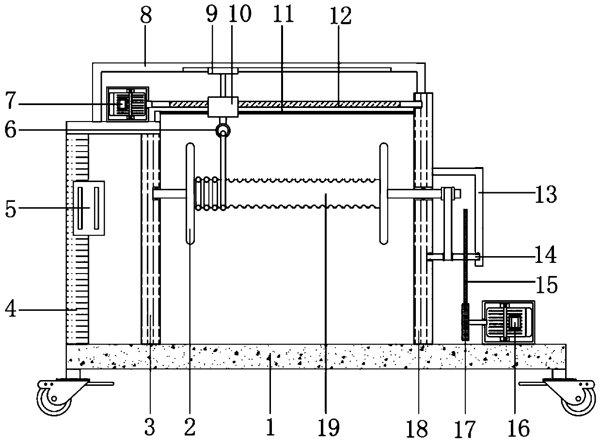
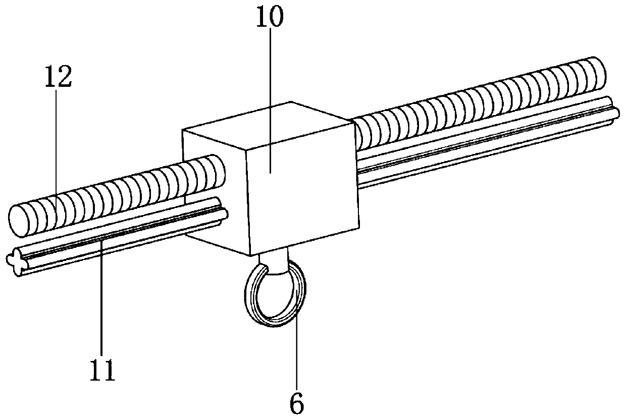
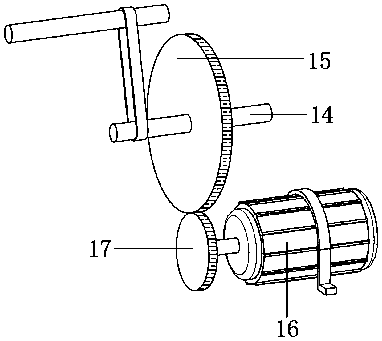

Image

  • Cable processing winding machine
  • Cable processing winding machine
  • Cable processing winding machine

Examples


Embodiment 1

[0027] refer to Figure 1-3 , a cable processing and winding machine, including a base 1 with brake wheels fixed at the four corners of the bottom by bolts, and vertically arranged side braces one 3 and two side braces 18 are respectively welded on both sides of the top of the base 1, and the side braces The opposite side of one 3 and side brace plate 2 18 is connected with the same take-up roller 19 through bearing rotation, and the side of base 1 close to side brace plate 2 18 is equipped with a driving mechanism, and the base 1 is close to side brace plate 1 3. One side is welded with a column 4, and the top of the column 4 and the side support plate-3 are welded with the same mounting plate, and the mounting plate is equipped with a reciprocating movement mechanism, and the reciprocating movement mechanism includes a forward and reverse motor fixed to the mounting plate by bolts 7. The output shaft of the forward and reverse motor 7 is connected to the screw rod 12 through...

Embodiment 2

[0036] refer to figure 1 , a cable processing and winding machine, compared with Embodiment 1, this embodiment also includes a mounting plate and a side support plate 2 18 equipped with a strengthening mechanism, and the strengthening mechanism includes a fixing frame 8 welded to the mounting plate and the side support plate 2 18 , the fixed frame 8 has a chute, the chute is slidably connected with a T-shaped slide bar 9, and the end of the T-shaped slide bar 9 is welded to the top of the moving block 10.

[0037] Working principle: When in use, the mutual cooperation between the fixed frame 8 and the T-shaped sliding rod 9 is used to effectively improve the stability of the moving block 10 when it moves back and forth through its position-limiting effect, which is beneficial to the cable winding.


PUM


Abstract

The invention discloses a cable processing winding machine. The cable processing winding machine comprises a base, wherein brake wheels are fixedly installed at the four corners of the bottom of the base, the two sides of the top of the base are respectively and fixedly provided with a first side supporting plate and a second side supporting plate which are vertically arranged, and the opposite sides of the first side supporting plate and the second side supporting plate are rotationally connected with the same winding roller through bearings; the sides, close to the second side supporting plate, of the base is provided with a driving mechanism, and the side, close to one side of the first side supporting plate, of the base is fixedly provided with a stand column; and the top end of the stand column and the top end of the first side supporting plate are fixedly provided with the same mounting plate, the mounting plate is provided with a reciprocating moving mechanism, and the reciprocating moving mechanism comprises a forward and reverse rotating motor fixedly mounted on the mounting plate. Under the control of a controller, by controlling the operation direction of the forward andreverse rotation motor, a lead screw and a sliding rod are matched to drive a moving block to reciprocate back and forth, and a cable is driven to move back and forth through a sleeve ring, so that the winding of the cable is tidy and orderly, and the advantage of preventing cable knotting is acheived.

Description

technical field [0001] The invention relates to the technical field of cable processing, in particular to a cable processing winding machine. Background technique [0002] The cable is usually a rope-like cable twisted by several or several groups of wires. Each group of wires is insulated from each other, and is often twisted around a center, and the entire outside is covered with a highly insulating covering. The cable has the characteristics of internal electrification and external insulation. Cables are currently widely used in many fields. The cable needs to use the winding machine in the process of processing [0003] For example, the utility model patent with the Chinese patent application number CN201820367599.6 discloses a cable processing and winding machine, including a base, a cable reel and a top frame, universal wheels are installed at both ends of the bottom of the base, and the base It is convex, and the left and right ends of the base are vertically provi...

Claims


Application Information

Patent Timeline
Patent Type & Authority Applications(China)
IPC IPC(8): B65H54/44B65H54/553B65H54/28B65H54/70
CPCB65H54/2818B65H54/44B65H54/553B65H54/70B65H2701/34
Inventor 王善荣
Owner 惠州市鑫弘诚电子科技有限公司
Learn More