Winder for cloth weaving machine

A technology of winder and woven fabric, applied in looms, textiles, winding strips, etc., can solve the problems of reduced failure rate, slow production efficiency, and high failure rate, and achieves reduced failure rate, guaranteed efficiency, and is not easy to slip. Effect

Inactive Publication Date: 2016-11-09
TIANJIN XUHUIHENGYUAN PLASTIC PACKAGING CORP
View PDF14 Cites 3 Cited by
  • Summary
  • Abstract
  • Description
  • Claims
  • Application Information

AI Technical Summary

Problems solved by technology

[0002] In industrial production, it is often necessary to pack the products produced, and most of the packaging is habitually packaged in woven bags. Therefore, in industrial production, the demand for woven bags is increasing year by year. For woven bag manufacturers, the production output of woven bags has increased. In order to maximize their production benefits, how to use existing equipment to improve production efficiency and improve the uniformity of winding at the same time has become a company However, due to the aging of the equipment and the structural inconsistency with the actual production requirements of the existing equipment, the production efficiency is slow and the failure rate is high. In view of this situation, the present invention proposes a weaving machine The winding machine is used to further improve the existing equipment. The combination of various improved parts makes the equipment achieve the effect of one plus one greater than two, which makes the winding more tidy and reduces the failure rate while producing with high efficiency. It is suitable for mass production of woven bags and has strong practicability

Method used

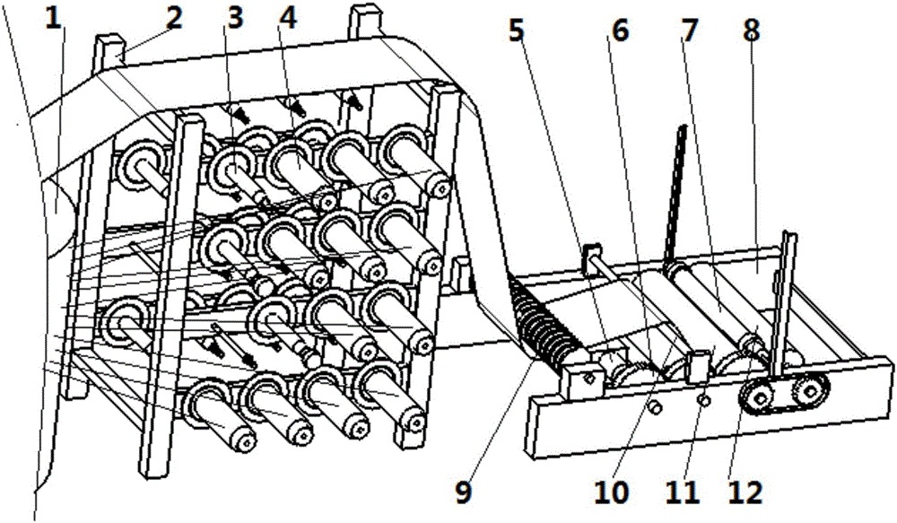
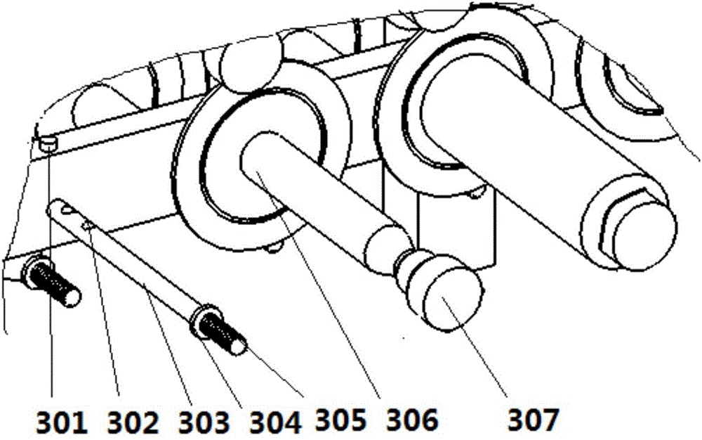
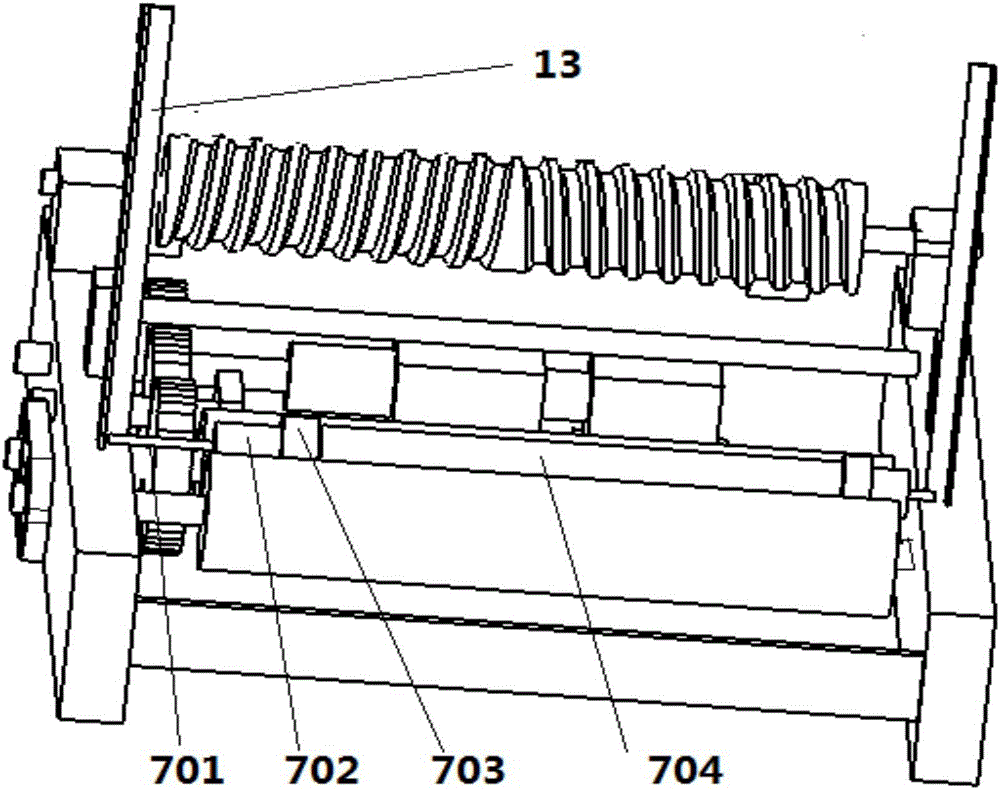

Image

  • Winder for cloth weaving machine
  • Winder for cloth weaving machine
  • Winder for cloth weaving machine

Examples


Embodiment Construction

[0030] It should be noted that, in the case of no conflict, the embodiments of the present invention and the features in the embodiments can be combined with each other.

[0031] In describing the present invention, it should be understood that the terms "center", "longitudinal", "transverse", "upper", "lower", "front", "rear", "left", "right", " The orientations or positional relationships indicated by "vertical", "horizontal", "top", "bottom", "inner" and "outer" are based on the orientations or positional relationships shown in the drawings, and are only for the convenience of describing the present invention and Simplified descriptions, rather than indicating or implying that the device or element referred to must have a particular orientation, be constructed and operate in a particular orientation, and thus should not be construed as limiting the invention. In addition, the terms "first", "second", etc. are used for descriptive purposes only, and should not be understood ...


PUM


Abstract

The invention provides a winder for a cloth weaving machine. The winder comprises a winder body and is divided into a wound silk placement portion and a cloth winding portion, the wound silk placement portion comprises a support, multiple wound silk supporting rods are arranged on the support, the cloth winding portion comprises an underframe, a driving mechanism, a transmission mechanism and a winding mechanism, and a first guide roller and a second guide roller are arranged on the underframe; each wound silk supporting rod comprises a fixed rod and a wound silk barrel, one end of each fixed rod is provided with a thread, a fixed block is arranged at the end of each thread, each wound silk barrel is arranged on the corresponding fixed rod, each fixed rod is fixed on the support, and a limiting device is arranged on the underframe and comprises an L-shaped retaining plate fixed on the underframe. The winder is formed by further improving existing equipment, thereby being high in production efficiency, more orderly in winding, lowered in fault rate, suitable for mass production of woven bags and high in practicability.

Description

technical field [0001] The invention belongs to the field of weaving machines, in particular to a winding machine for a weaving machine. Background technique [0002] In industrial production, it is often necessary to pack the products produced, and most of the packaging is habitually packaged in woven bags. Therefore, in industrial production, the demand for woven bags is increasing year by year. For woven bag manufacturers, the production output of woven bags has increased. In order to maximize their production benefits, how to use existing equipment to improve production efficiency and improve the uniformity of winding at the same time has become a company However, due to the aging of the equipment and the structural inconsistency with the actual production requirements of the existing equipment, the production efficiency is slow and the failure rate is high. In view of this situation, the present invention proposes a weaving machine The winding machine is used to furthe...

Claims


Application Information

Patent Timeline
Patent Type & Authority Applications(China)
IPC IPC(8): B65H49/32B65H18/20B65H23/34D03D49/20
CPCB65H49/32B65H18/20B65H23/34B65H2403/40B65H2403/41B65H2701/31D03D49/20
Inventor 王旭辉
Owner TIANJIN XUHUIHENGYUAN PLASTIC PACKAGING CORP
Why Eureka
Try Eureka