Water distillation system and water distillation method
A technology of water distillation and evaporator, applied in the field of water distillation system, can solve problems such as heat exchanger structural failure, system efficiency reduction, failure, etc., and achieve the effect of accelerating water evaporation, less energy consumption, and simple method
- Summary
- Abstract
- Description
- Claims
- Application Information
AI Technical Summary
Problems solved by technology
Method used
Image

Examples
Embodiment approach
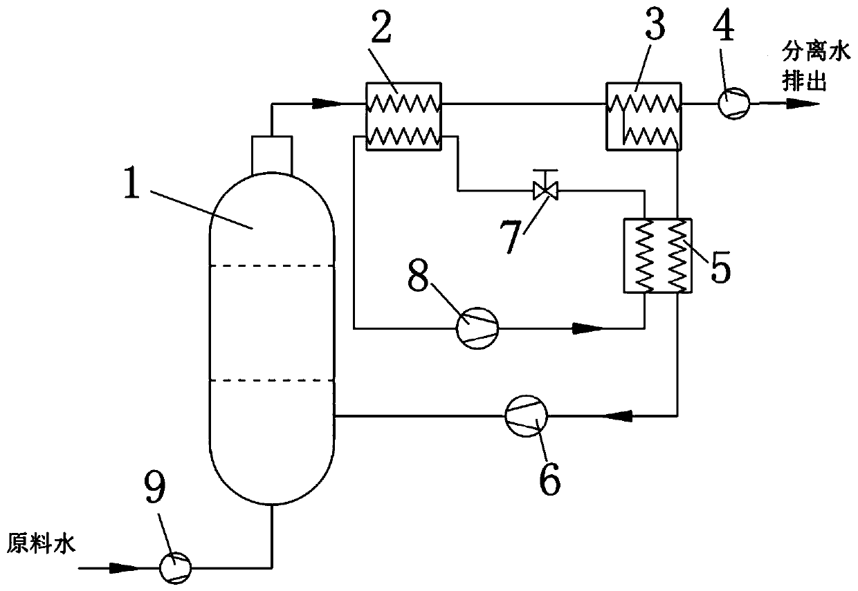
[0031] A water distillation system comprising a gas cycle and a heat pump cycle;
[0032] The gas cycle includes an evaporator 1, the upper outlet of the evaporator 1 is connected to the first channel inlet of the dehumidifier 2, and the first channel outlet of the dehumidifier 2 is connected to the inlet of the separator 3, and the outlet of the separator 3 is divided into a gas outlet and a drain outlet , the gas outlet of the separator 3 is connected to the gas circulation inlet of the regenerator 5, and the gas circulation outlet of the regenerator 5 is connected to the lower inlet of the evaporator 1;
[0033] The heat pump cycle includes a compressor 8, the outlet of the compressor 8 is connected to the heat pump cycle inlet of the regenerator 5, the heat pump cycle outlet of the regenerator 5 is connected to the second channel inlet of the dehumidifier 2 through the expansion valve 7, and the second channel inlet of the dehumidifier 2 The channel outlet is connected to ...
Embodiment 1
[0045] like figure 1 As shown, the gas cycle includes an evaporator 1, and the circulating gas is heated in the evaporator 1 to evaporate water, and then enters the dehumidifier 2 for dehumidification after forming a saturated wet gas, and then enters the separator 3 for separation; after the separator 3, a drainage pump 4 is arranged to The separated liquid water is discharged out of the system; the circulating gas separated by the separator 3 enters the regenerator 5 to be heated, and the humidity is reduced, and then driven by the gas cycle machine 6, and enters the evaporator 1 to form a cycle; the inlet of the evaporator 1 is provided with a The water pump 9 sends the raw material water into the evaporator 1. The heat pump cycle includes a compressor 8. The low-temperature and low-pressure heat pump cycle working fluid absorbs heat in the dehumidifier 2, and is then compressed by the compressor 8 to become a high-temperature and high-pressure working fluid, and then enter...
Embodiment 2
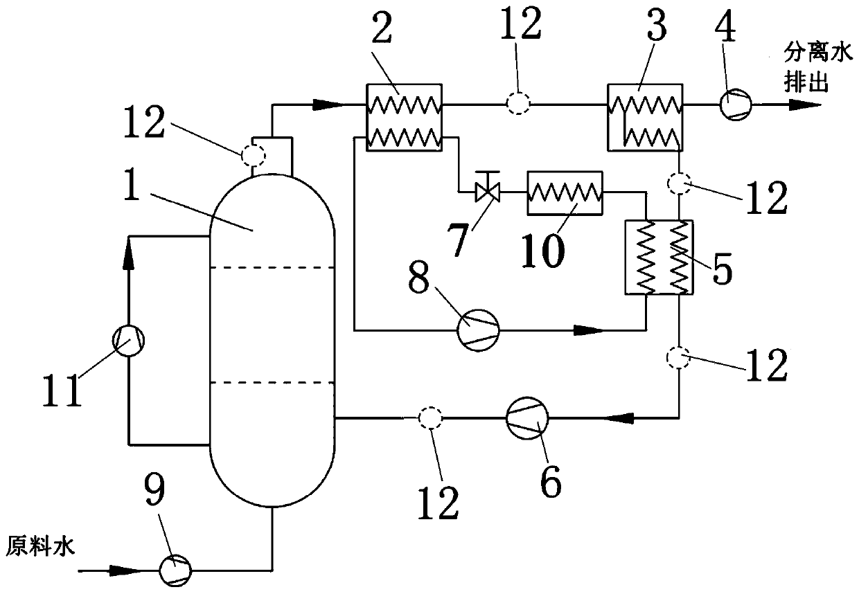
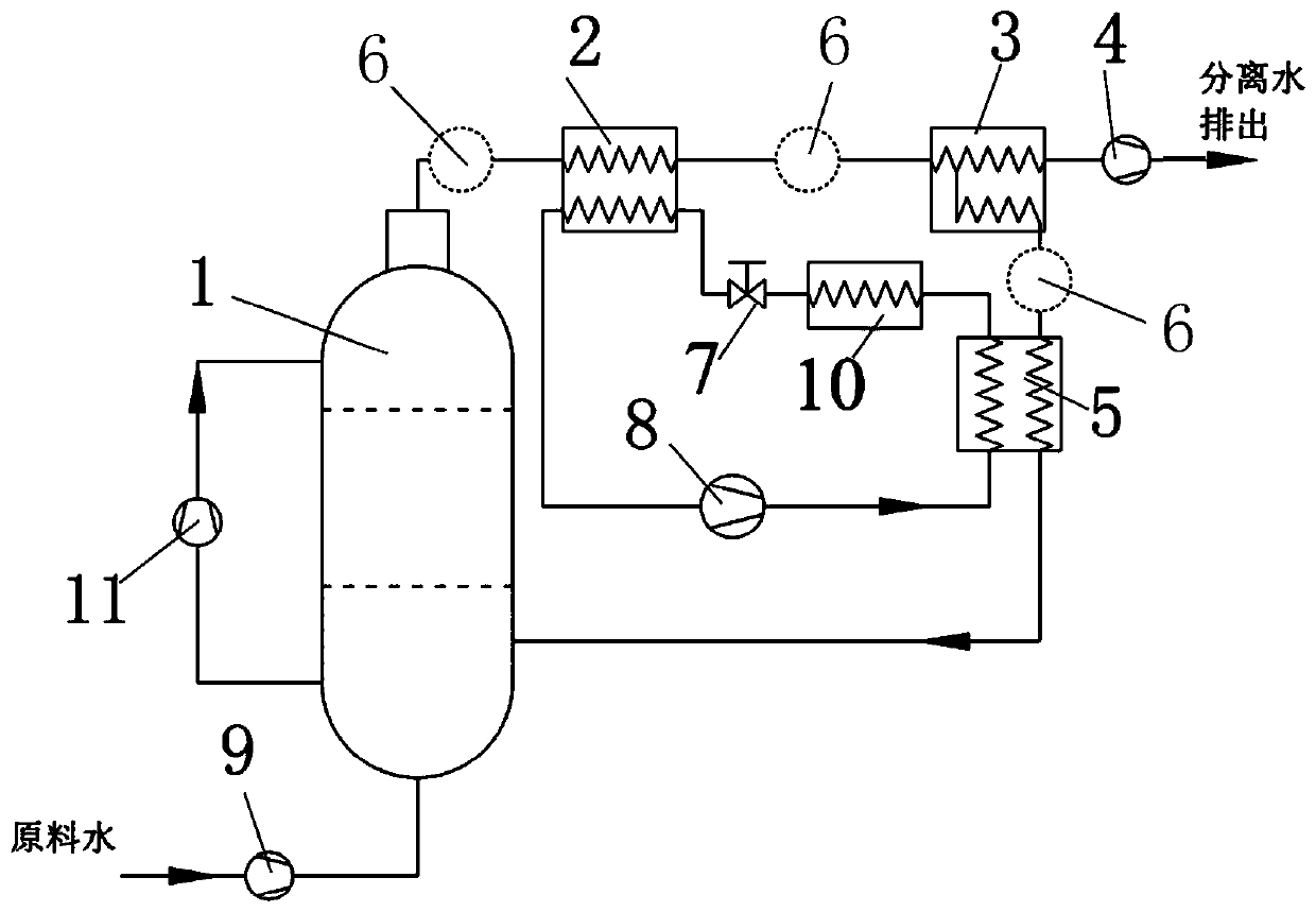
[0048] like figure 2As shown, the gas cycle includes an evaporator 1, and the circulating gas is heated in the evaporator 1 to evaporate water, and then enters the dehumidifier 2 for dehumidification after forming a saturated wet gas, and then enters the separator 3 for separation; after the separator 3, a drainage pump 4 is arranged to The separated liquid water is discharged out of the system; the circulating gas separated by the separator 3 enters the regenerator 5 to be heated, and the humidity is reduced, and then driven by the gas cycle machine 6, and enters the evaporator 1 to form a cycle; the inlet of the evaporator 1 is provided with a The water pump 9 sends the raw material water into the evaporator 1. The heat pump cycle includes a compressor 8. The low-temperature and low-pressure heat pump cycle fluid absorbs heat in the dehumidifier 2, and is then compressed by the compressor 8 to become a high-temperature and high-pressure fluid, and then enters the heater 5; ...
PUM
 Abstract
Description
Claims
Application Information
 - R&D Engineer
- R&D Manager
- IP Professional
- Industry Leading Data Capabilities
- Powerful AI technology
- Patent DNA Extraction
Browse by: Latest US Patents, China's latest patents, Technical Efficacy Thesaurus, Application Domain, Technology Topic.
© 2024 PatSnap. All rights reserved.Legal|Privacy policy|Modern Slavery Act Transparency Statement|Sitemap