
Large-cantilever prestressed-cover-beam support device and construction method

A support device and prestressing technology, applied in the direction of bridges, bridge construction, erection/assembly of bridges, etc., can solve the problems of affecting the pouring quality of cover beams, large deformation, and small investment in steel consumption, so as to solve the contradiction of cast-in-place construction, The effect of safe construction and less steel consumption

Inactive Publication Date: 2020-02-21
ZHEJIANG UNIV CITY COLLEGE +1
View PDF8 Cites 13 Cited by
  • Summary
  • Abstract
  • Description
  • Claims
  • Application Information

AI Technical Summary

Problems solved by technology

[0003] According to the existing engineering practice, the large cantilever cover beam mainly uses the support form of the steel pipe support column plus the Bailey frame, or the steel pipe support column plus the cantilever truss type support system or the corbel bracket plus the Bailey frame and other forms, and its advantages are as follows: Make full use of the cap to set up steel pipe support columns for support erection, the construction process will not affect the normal driving of vehicles within the projection range of the cover beam, and the amount of steel used for the temporary structure is relatively small, and the construction is convenient; the disadvantage is that the support system is limited by the cantilever length of the cover beam When the cantilever length exceeds 8m, the deformation of the cantilever Bailey frame support or truss on the steel pipe column or bracket will be large, which will affect the pouring quality of the cover beam

Method used


Image

  • Large-cantilever prestressed-cover-beam support device and construction method
  • Large-cantilever prestressed-cover-beam support device and construction method

Examples


Embodiment 1

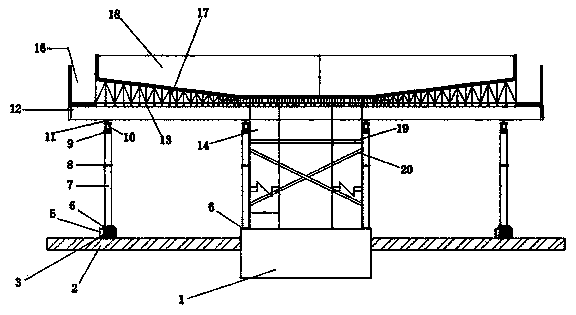
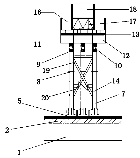
[0026] Such as figure 1 , 2 As shown, a large cantilever prestressed cover beam support device includes a middle support column supported on the cantilever root of the cover beam 18, and the middle support column is symmetrically arranged on both sides of the cover beam 18 piers 14, and the bottom of the middle support column It is supported on the cap 1 where the pier column of the cover beam 18 is located; it also includes an end support column supported on the cantilever end of the cover beam 18, the bottom end of the end support column is supported on the ground by reinforced concrete 5, and the middle part The upper ends of the support column and the end support column support the load-bearing beam, and the load-bearing beam supports the slope adjustment truss beam 17, and the slope adjustment truss beam 17 supports the bottom mold of the cover beam 18 on the upper end. Vehicles can pass between the middle support pillar and the end support pillar. The middle support co...


PUM


Abstract

The invention provides a large-cantilever prestressed-cover-beam support device and a construction method, and relates to a road-bridge cover-beam construction device. The problem that in the prior art, a large-cantilever cover-beam supporting system influences the road traffic under a bridge is solved. The large-cantilever prestressed-cover-beam support device comprises middle supporting columnssupported at the root of a cover-beam cantilever, the middle supporting columns are symmetrically arranged on the two sides of a cover-beam pier, and the bottoms of the middle supporting columns are supported on a bearing platform where the cover-beam pier is located. The large-cantilever prestressed-cover-beam support device further comprises end supporting columns supported at the end of the cover-beam cantilever, the bottoms of the end supporting columns are supported on the ground through reinforced concrete, a bearing beam is supported at the upper ends of the middle supporting columns and the upper ends of the end supporting columns, a slope-adjusting truss beam is supported on the bearing beam, and a cover-beam bottom die is supported on the slope-adjusting truss beam. By designinga gate pier type assembly type steel pipe supporting column support system, the contradiction between normal passing on a ground road and cast-in-place construction of the cantilever cover beam is well solved, and the steel consumption of a temporary structure is small.

Description

technical field [0001] The invention belongs to the technical field of building construction, and relates to a construction device for road bridge cover beams, in particular to a road bridge cover beam support device. Background technique [0002] With the continuous development of urban viaduct construction, large cantilever prestressed concrete cap beams have been widely used due to their advantages such as small footprint, light structure, beautiful appearance, good traffic sightlines and full use of urban road space. In order to alleviate the increasingly tense traffic pressure, urban roads and viaducts have been built wider and wider. The total length of the cover beams has exceeded 35m, and the length of the cantilever on one side has gradually reached more than 10m. In order to minimize the impact on road traffic under the bridge, higher requirements are put forward for the construction of large cantilever cap beams. [0003] According to the existing engineering pra...

Claims


Application Information

Patent Timeline
IPC IPC(8): E01D21/00
CPCE01D21/00
Inventor 周联英王建勋施可成缪国波奉小华叶水标翟骥腾施露赵庆奎李盖盖任致桦
Owner ZHEJIANG UNIV CITY COLLEGE
Learn More