
Fault monitoring system for mine shaft and method

A fault monitoring and wellbore technology, which is applied in the field of transmission systems, can solve problems such as wasting time and danger, and achieve the effects of convenient construction and fixation, small size, and improved maintenance engineering volume and safety

Active Publication Date: 2020-02-21
QINGDAO TECHNOLOGICAL UNIVERSITY
View PDF4 Cites 5 Cited by
  • Summary
  • Abstract
  • Description
  • Claims
  • Application Information

AI Technical Summary

Problems solved by technology

[0005] Chinese invention patent CN201110218602.0 discloses a coal mine underground fire monitoring system based on a wireless sensor network, including a monitoring host, a communication master station, and a wireless sensor network. The wireless sensor network communicates with the monitoring host through the communication master station. The sensor network is a ZigBee wireless self-organizing network. The wireless sensors include wireless carbon monoxide sensors, wireless wind pressure sensors and wireless temperature sensors, which can timely and accurately monitor coal mine underground fires, and can effectively control the energy consumption of wireless sensor network nodes, extending wireless The service life of the sensor network, but the monitoring system is mainly used for fire monitoring, but in practical applications, especially in mine shafts, there are many abnormalities that affect actual production, such as tilting, collapse, accidental drop, dust diffusion, and When an abnormality occurs, maintenance personnel are often required to go down the well to check without accurate information, which not only wastes time but also poses certain dangers

Method used


Image

  • Fault monitoring system for mine shaft and method
  • Fault monitoring system for mine shaft and method
  • Fault monitoring system for mine shaft and method

Examples


Embodiment Construction

[0042] The following will clearly and completely describe the technical solutions in the embodiments of the present invention with reference to the accompanying drawings in the embodiments of the present invention. Obviously, the described embodiments are only some, not all, embodiments of the present invention. Based on the embodiments of the present invention, all other embodiments obtained by persons of ordinary skill in the art without making creative efforts belong to the protection scope of the present invention.

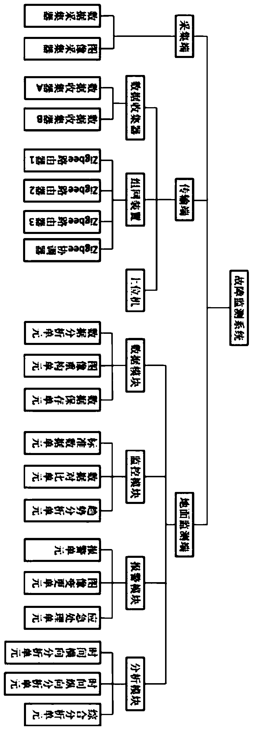
[0043] See figure 1 , a fault monitoring system for mine shafts, including a collection end, a transmission end, and a ground monitoring end. A control station for analyzing, organizing, and judging data.

[0044] Acquisition end

[0045] The acquisition terminal is mainly used to collect two forms of data, one is digital quantitative data, such as temperature, pressure, etc., and the other is image data, so the whole includes a data collector and an image c...


PUM


Abstract

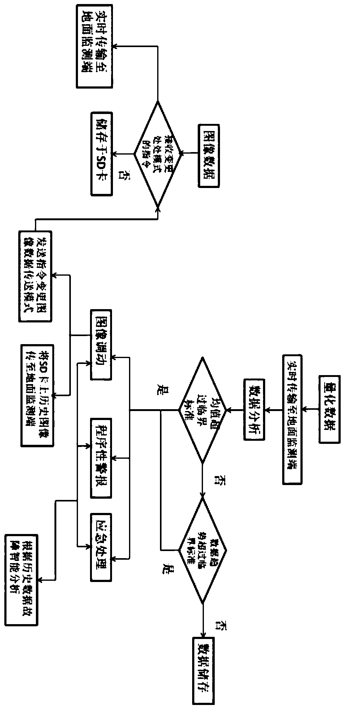
The invention discloses a fault monitoring system for a mine shaft. The system comprises a collection end, a transmission end and a ground monitoring end. The collection end is mainly used for collecting required data at the mine shaft; the transmission end is designed based on ZigBee, and is a network structure used for transmitting data; and the ground monitoring end is an intelligent control station used for analyzing, sorting and judging data, can collect various kinds of performance and environment data of the mine shaft, achieves the functions of automatic analysis, monitoring, storage,alarming and fault recognition, has a unique trend comparison mode, can conduct monitoring and predicting in the early stage of hidden danger, and automatically calls relevant image data after an abnormal condition occurs to provide sufficient data for engineers to carry out ground analysis, in this way, the maintenance engineering amount is increased, and the safety is improved.

Description

technical field [0001] The invention relates to the technical field of transmission systems, in particular to a fault monitoring system and method for mine shafts. Background technique [0002] Existing mines, especially non-metallic mines, mostly adopt the mining method of shafts, and the depth of shafts ranges from 500-1000m. The freezing method is usually used in the wellbore construction process, and the vertical additional force of the wellbore was not considered in the early wellbore design, so the wellbore that has been in service for a long time is most prone to shear failure. In order to ensure the safety during the operation of the mine, as the shaft of the non-metallic mine throat, it is necessary to keep abreast of the stability of the shaft at all times, and the monitoring system is usually arranged horizontally in the shaft to monitor the deformation and stress of the concrete on the shaft wall in real time. The different monitoring points of the ground are co...

Claims


Application Information

Patent Timeline
IPC IPC(8): E21F17/18E21F17/00G01D21/02G08C17/02H04N5/225H04W4/80
CPCE21F17/18E21F17/00G01D21/02G08C17/02H04W4/80H04N23/54H04N7/181H04L67/12H04W4/38H04W4/90E21D7/005H04N23/57
Inventor 丛宇张黎明王在泉
Owner QINGDAO TECHNOLOGICAL UNIVERSITY
Learn More