Compressor fixing assembly and compressor

A technology for fixing components and compressors, applied in the field of compressors, can solve problems such as the limitation of vibration reduction and vibration isolation effects, and achieve the effects of reducing internal stress, improving vibration isolation and vibration reduction effects, and increasing contact area.

Pending Publication Date: 2020-02-21
北京比维柯制冷设备有限公司
View PDF6 Cites 0 Cited by
  • Summary
  • Abstract
  • Description
  • Claims
  • Application Information

AI Technical Summary

Problems solved by technology

[0003] Because the rubber pad itself has good elasticity and ductility, it can absorb part of the vibration during the operation of the compressor, but it is also because of this characteristic of the rubber pad that it is affected by the vibration of the compressor body during use. Due to the action of gravity, and because the contact area between the rubber pad and the foot is usually flat, this makes the rubber pad bear a lot of pressure and concentrate its internal stress, and the effect of vibration damping and vibration isolation is greatly limited.

Method used


Image

  • Compressor fixing assembly and compressor
  • Compressor fixing assembly and compressor
  • Compressor fixing assembly and compressor

Examples


Embodiment 1

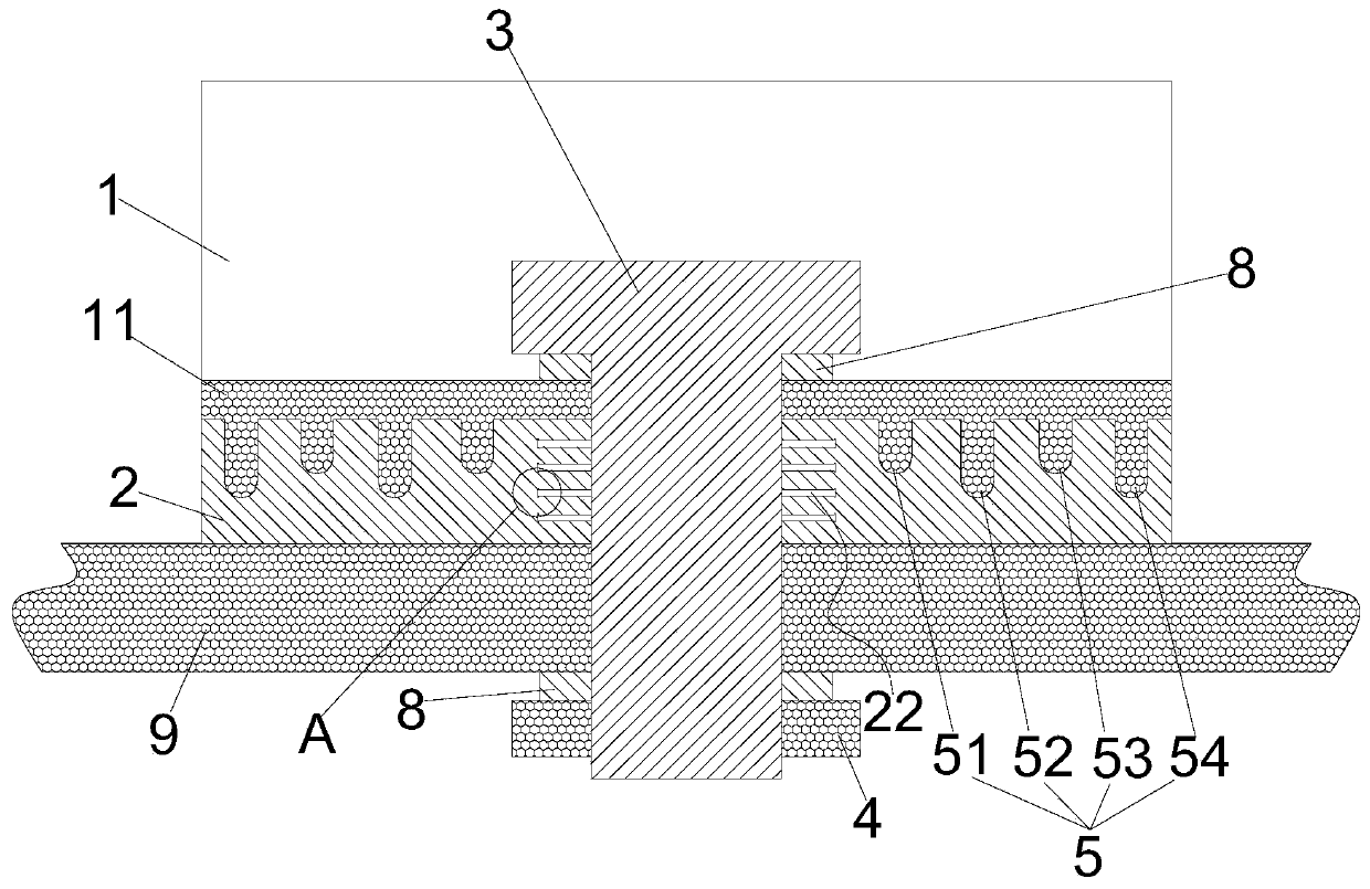
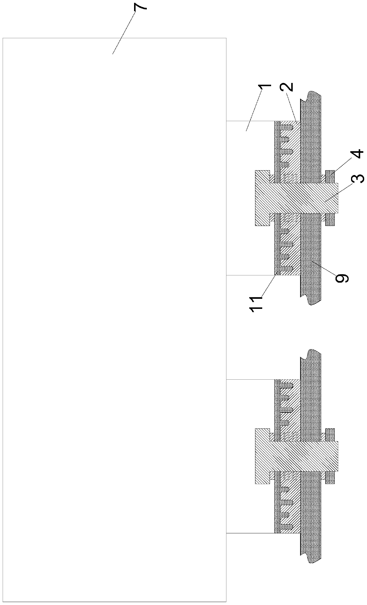
[0037] This embodiment provides a compressor fixing assembly for fixing and installing a compressor, including a foot 1, a rubber pad 2, a screw 3 and a nut 4. The foot 1 is fixed on the body 7 of the compressor and the foot 1 is compatible with The body 7 of the compressor is an integral structure, and the support foot 1 at least includes a flat plate 11, the flat plate 11 is provided with a first through hole 12, and the rubber pad 2 is provided with a second through hole 21, and the rubber pad 2 is in the shape of a square .

[0038] During installation, the above-mentioned plate 11 is overlapped on the rubber pad 2, that is, the rubber pad 2 is placed under the above-mentioned plate 11, and the first through hole 12 and the second through hole 21 are facing each other, and the screws 3 pass through the first through hole in turn. The hole 12 and the second through hole 21 are then screwed to the nut 4 . More preferably, a washer 8 is provided between the nut 4 and the rubb...

Embodiment 2

[0042] This embodiment serves as a specific implementation of Embodiment 1. The several protrusions 5 in the compressor fixing assembly provided by this embodiment are divided into an inner group and an outer group, and the inner group has a plurality of protrusions 5 Sector-shaped protrusions, a plurality of sector-shaped protrusions are equidistantly distributed and surround a first ring 51, and the first ring 51 is coaxial with the first through hole 12. Optimally, the number of the above-mentioned sector-shaped protrusions is four , the central angle of each fan-shaped bump is 45°.

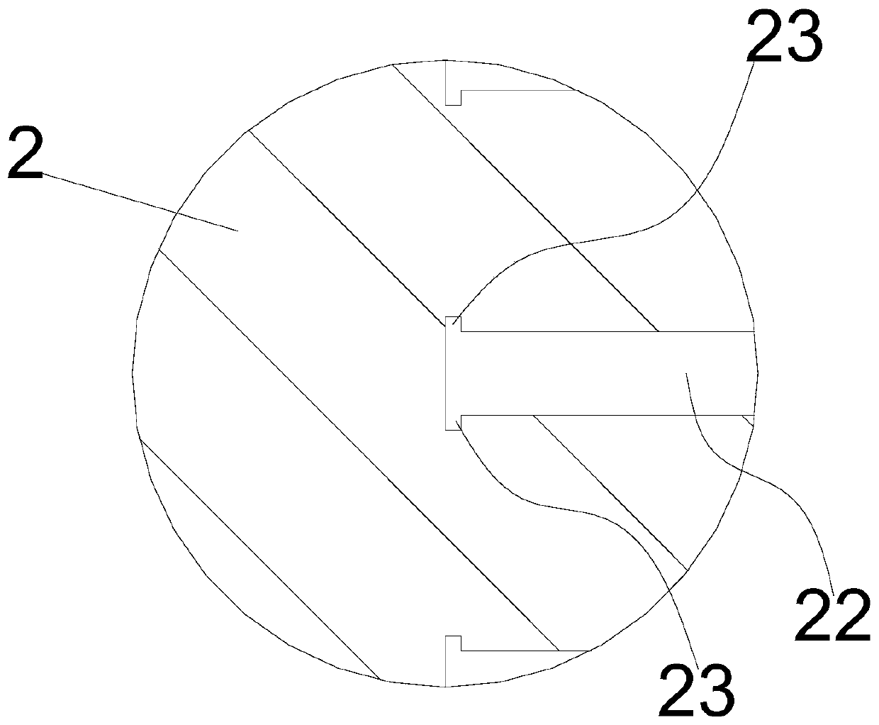
[0043] The ravine 6 on the above-mentioned rubber pad 2 includes a first groove adapted to the above-mentioned first ring 51, the first groove includes four fan-shaped grooves, and the four fan-shaped protrusions of the above-mentioned first ring 51 are respectively embedded in four In the fan-shaped groove, in this way, the vibration of the support foot 1 can be transmitted to the first groov...

Embodiment 3

[0046] This embodiment is a best implementation mode of the above-mentioned embodiment. In this embodiment, there are also multiple ring-shaped bumps, and the diameters of the multiple ring-shaped bumps increase sequentially from inside to outside. Optimally, the number of the above-mentioned ring-shaped protrusions is three, and the order from inside to outside is the second ring 52, the third ring 53 and the fourth ring 54. The height is a, the height of the second ring 52 is b, the height of the third ring 53 is c, and the height of the fourth ring 54 is d, wherein a=c, b=d, d>c. In this case, the above-mentioned second groove also includes three circular grooves, and the function of each circular groove can also reduce the effect of vibration transmitted along the radial direction of the rubber pad 2 .

[0047] With this structure, all the protrusions 5 form a wave-shaped structure from the outside to the inside, so that when subjected to vibration, each ring is limited by...


PUM


Abstract

The invention relates to a compressor fixing assembly and a compressor and belongs to the technical field of compressors. The compressor fixing assembly comprises a stand bar, a rubber blanket, a screw and a nut, wherein the stand bar at least comprises a plate; a first through hole is formed in the plate; a second through hole is formed in the rubber blanket; the rubber blanket is put under the plate; the first through hole directly faces the second through hole; the screw sequentially penetrates through the first through hole and the second through hole to be in screw joint with the nut; a plurality of bulges are arranged on the face, in contact with the rubber blanket, of the plate; a plurality of gullies are arranged on the face, in contact with the plate, of the rubber blanket; and one bulge is mounted in each gully in a clamping manner; and the bulge and the corresponding gully are matched in shape and size. The compressor comprises a compressor body and the compressor fixing assembly. The compressor fixing assembly with the structure has the advantages of better vibration isolating and reducing effect and longer service life. The compressor has the advantage of smaller vibration during the operation process.

Description

technical field [0001] The invention belongs to the technical field of compressors, in particular to a compressor fixing assembly and a compressor. Background technique [0002] When the compressor is fixedly installed, in order to play the role of shock absorption and isolation, rubber pads are usually placed under the feet of the compressor, and the fastening screws pass through the feet and rubber pads in turn. During the compression process, the fastening screws are used to The pre-tightening force of the screw connection with the nut, so that the foot and the rubber pad are pressed together. [0003] Because the rubber pad itself has good elasticity and ductility, it can absorb part of the vibration during the operation of the compressor, but it is also because of this characteristic of the rubber pad that it is affected by the vibration of the compressor body during use. Due to the action of gravity, and because the contact area between the rubber pad and the foot is ...

Claims


Application Information

Patent Timeline
Patent Type & Authority Applications(China)
IPC IPC(8): F04B39/00
CPCF04B39/00F04B39/0044
Inventor 梁忠海
Owner 北京比维柯制冷设备有限公司
Why Eureka
Try Eureka