Snake-shaped wellhead viscosity reduction device based on coupling effect

A serpentine and viscosity-reducing technology, applied in the direction of engine seals, engine components, pipeline systems, etc., can solve the problem of inability to disperse and propel the crude oil, and achieve the effect of preventing crude oil clogging, preventing adhesion and accumulation, and convenient installation and disassembly.

Pending Publication Date: 2020-02-21
HEILONGJIANG LANDE ULTRASONIC TECH CO LTD
View PDF8 Cites 0 Cited by
  • Summary
  • Abstract
  • Description
  • Claims
  • Application Information

AI Technical Summary

Problems solved by technology

However, this equipment cannot break up the crude oil at the bend of the serpentine pipeline

Method used


Image

  • Snake-shaped wellhead viscosity reduction device based on coupling effect
  • Snake-shaped wellhead viscosity reduction device based on coupling effect
  • Snake-shaped wellhead viscosity reduction device based on coupling effect

Examples


specific Embodiment approach 1

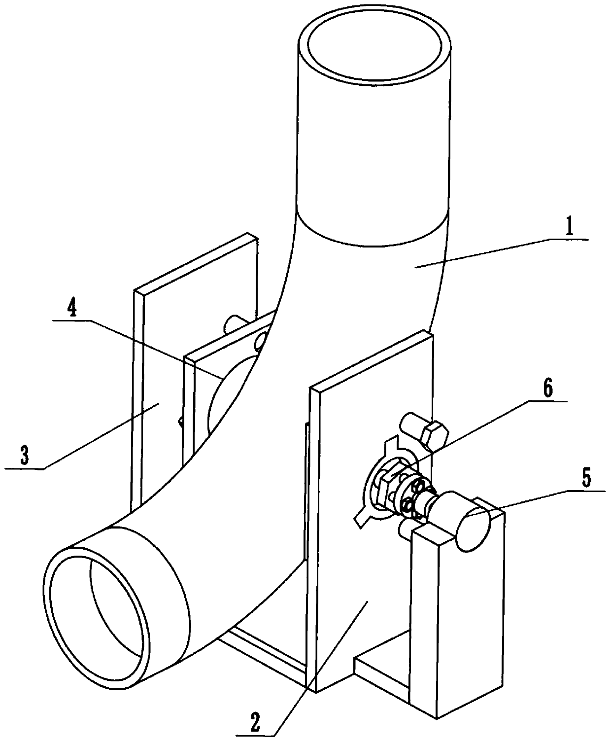
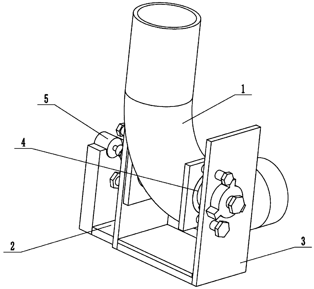
[0033] Such as Figure 1 to Figure 13As shown, a serpentine wellhead viscosity reduction device based on coupling, including a serpentine bend pipe 1, a right propulsion fixing seat 2, a left propulsion fixing seat 3, two sealing seats 4, a propulsion driver 5 and a drive regulator 6 , the left push fixed seat 3 is slidably connected to the right push fixed seat 2, and the two sealing seats 4 are connected to the left push fixed seat 3 and the right push fixed seat 2 respectively by threaded fit, and the inside of the two seal seats 4 Both ends are fitted on the serpentine curved pipe 1, the right end of the propulsion driver 5 is fixedly connected to the right propulsion fixing seat 2, and the propulsion driver 5 is clearance-fitted on the right propulsion fixing seat 2 and the left propulsion fixing seat 3, and the propulsion driver 5 Connected in the two sealing seats 4 through the sealing thread, the propulsion driver 5 rotates in the serpentine curved pipe 1, the right en...

specific Embodiment approach 2

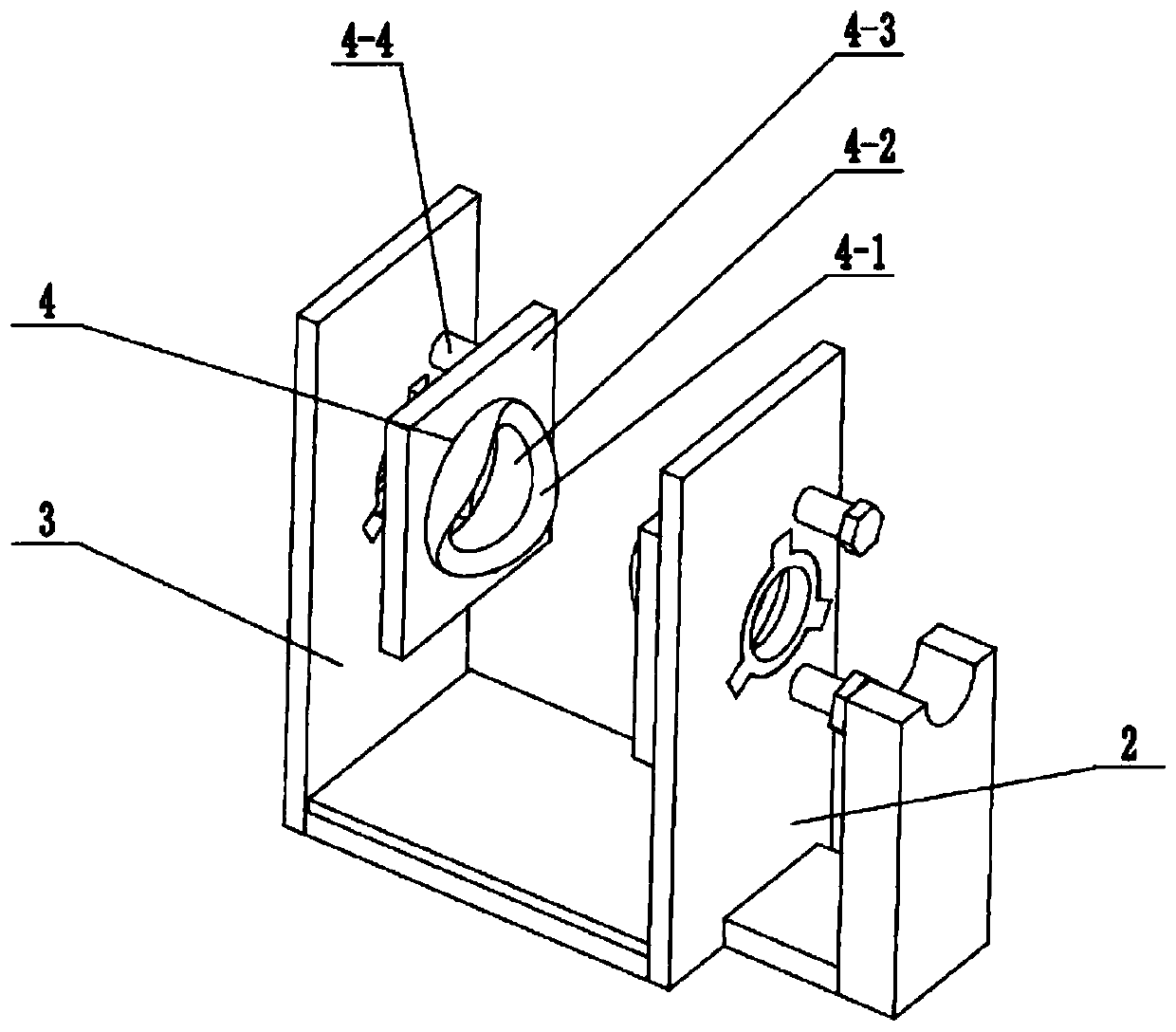
[0035] Such as Figure 1 to Figure 13 As shown, this embodiment further describes the first embodiment, and the left and right ends of the bend of the serpentine pipe 1 are provided with communicating circular openings. It is convenient for the insertion of the device for breaking and stirring.

specific Embodiment approach 3

[0037] Such as Figure 1 to Figure 13 As shown, this embodiment will further explain the second embodiment. The right pusher fixing seat 2 includes a lower bottom plate 2-1, a combined sliding T-shaped slot 2-2, a right limit fixing plate 2-3, a right limit The hole 2-4 and the motor holder 2-5, the right end of the lower base plate 2-1 are fixedly connected to the lower end of the right limit fixed plate 2-3, the combined sliding T-shaped groove 2-2 is arranged on the lower base plate 2-1, the right The limit hole 2-4 is arranged on the right limit fixed plate 2-3, and the right end of the right limit fixed plate 2-3 is fixedly connected to the motor holder 2-5.


PUM


Abstract

The invention relates to the field of crude oil viscosity reduction, in particular to a snake-shaped wellhead viscosity reduction device based on coupling effect. The device comprises a coiled pipe bending pipe, a right propulsion fixing base, a left propulsion fixing base, two sealing seats, a propulsion driver and a driving regulator; and the left propulsion fixing base is connected to the rightpropulsion fixing base in a sliding mode, the two sealing seats are connected to the left propulsion fixing base and the right propulsion fixing base in a threaded fit mode correspondingly, the innerends of the two sealing seats are attached to the coiled pipe bending pipe, and the right end of the propulsion driver is fixedly connected to the right propulsion fixing base. The snake-shaped wellhead viscosity reduction device based on the coupling effect has the beneficial effects that crude oil can be scattered and propelled at the bending position of a snake-shaped pipeline where the crudeoil is prone to accumulate, so that the situation that the crude oil transportation is influenced due to the fact that the crude oil adheres and accumulates at the bending position of the snake-shapedpipeline is prevented; and installation and disassembly are extremely convenient, and the device can be used for carrying out relay type propulsion on the crude oil in the snake-shaped pipeline, so that crude oil blockage caused by insufficient transportation power is prevented.

Description

technical field [0001] The invention relates to the field of crude oil viscosity reduction, in particular to a coupling-based serpentine wellhead viscosity reduction device. Background technique [0002] The patent number is CN200810114742.1, which discloses a pipeline composite magnetic field wax prevention and viscosity reduction treatment device, which is applied to wax removal in crude oil transportation pipelines. The characteristics are: a suspension plate is fixed between the pipe flanges, there is a magnetic core fixing hole in the center of the suspension plate, and there are crude oil channel holes around the fixing hole, the threaded fixing head at the end of the magnetic core passes through the fixing hole of the suspension plate, and is connected with a flow nut. The magnetic core is fixed on the suspension plate, the center line of the magnetic core is vertical to the hanging plate, and there is a push-magnetic high-frequency cable winding formed by winding ins...

Claims


Application Information

Patent Timeline
IPC IPC(8): F17D1/16F16J15/06F16J15/16
CPCF16J15/061F16J15/16F17D1/16
Inventor 陈光甡李园初思瑶张修全赵宪忠黄滨武明杰
Owner HEILONGJIANG LANDE ULTRASONIC TECH CO LTD
Why Eureka
Try Eureka