
Scanning frame and path planning method thereof

A path planning and scanning frame technology, which is applied in vehicle position/route/height control, instruments, measuring devices, etc., can solve problems such as heavy workload, physical and mental exhaustion, and limited length of automatic scanning frame to achieve detection omissions low rate effect

Active Publication Date: 2020-02-21
宁波市劳动安全技术服务有限公司
View PDF8 Cites 3 Cited by
  • Summary
  • Abstract
  • Description
  • Claims
  • Application Information

AI Technical Summary

Problems solved by technology

The non-destructive testing of tank welds and C-scan testing of the bottom plate all require manual testing and scanning with specific equipment, so the workload is relatively large, which will cause certain fatigue to the human body and mind
[0003] Therefore, in the prior art, there is an automatic scanning frame to reduce the workload of personnel. The automatic scanning frame is set on the hydraulic trolley through the probe, and the motor drives the hydraulic trolley to reciprocate horizontally, so as to clean the bottom plate of the storage tank. However, due to the limited length of the automatic scanning frame, only a part of the storage tank floor can be measured at a time, and the automatic scanning frame needs to be manually moved to measure the next area, which will still increase the workload of the staff

Method used


Image

  • Scanning frame and path planning method thereof
  • Scanning frame and path planning method thereof
  • Scanning frame and path planning method thereof

Examples


Embodiment Construction

[0032] The technical solutions of the various embodiments of the present invention will be clearly and completely described below in conjunction with the accompanying drawings. Apparently, the described embodiments are only some of the embodiments of the present invention, not all of them. Based on the embodiments described in the present invention, all other embodiments obtained by persons of ordinary skill in the art without creative efforts are within the protection scope of the present invention.

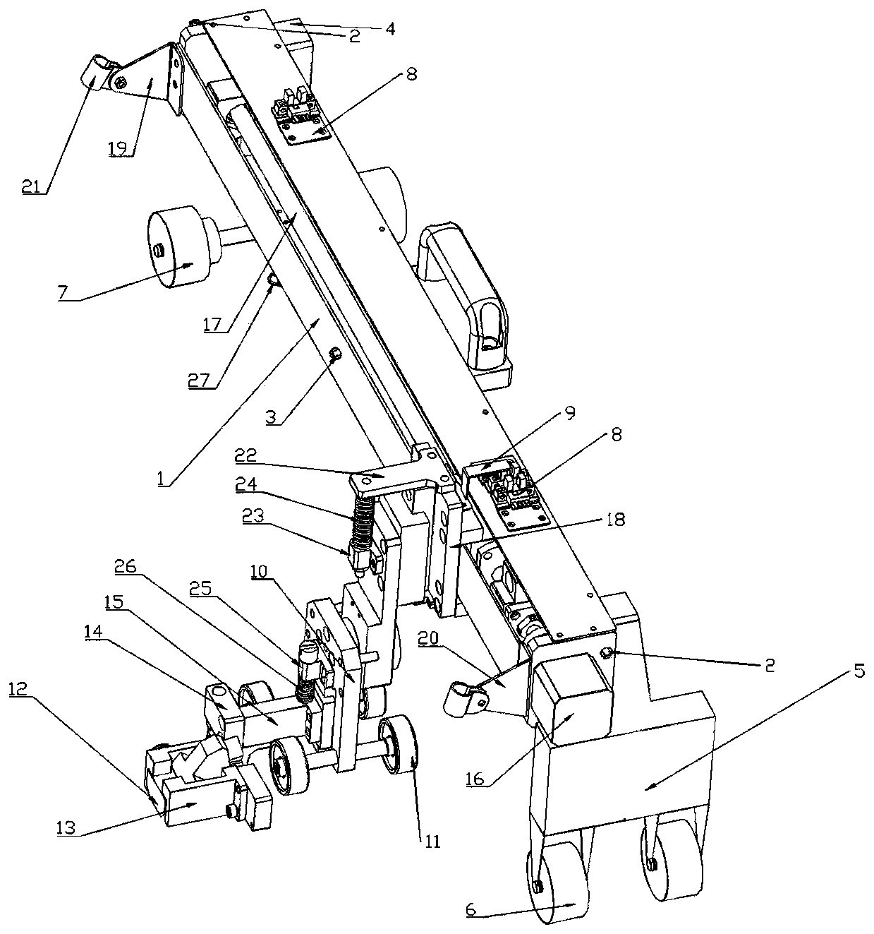
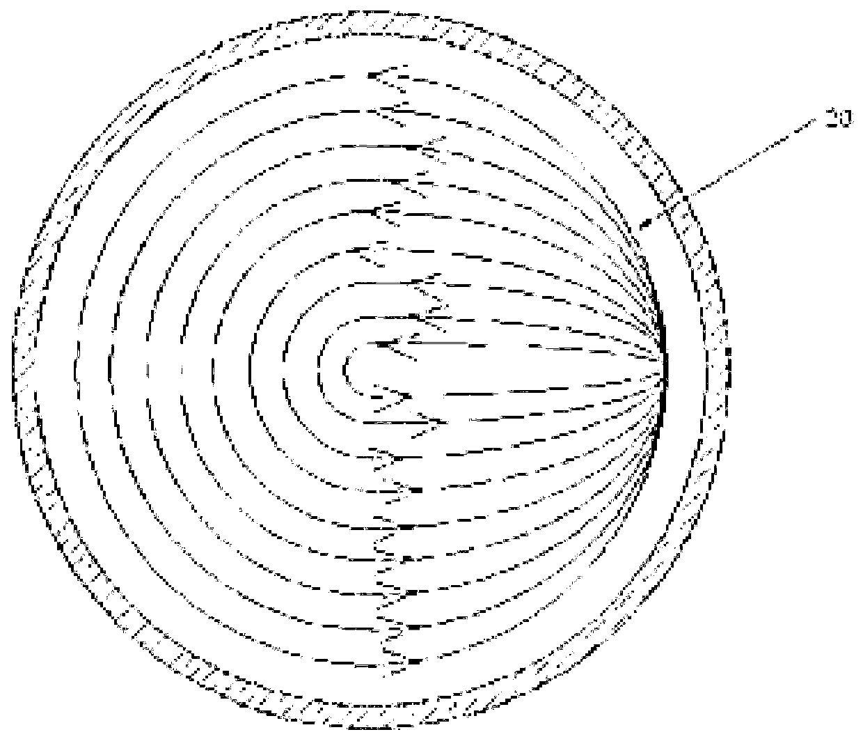
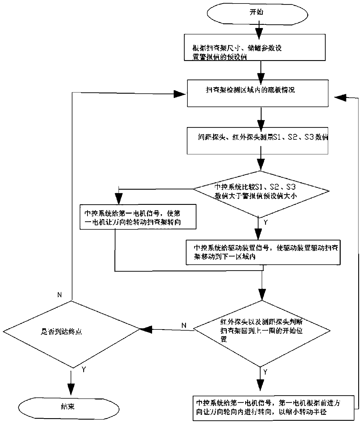
[0033] Embodiments of the present invention, such as Figure 1 to Figure 3As shown, a scanning frame is provided, including a central control system, a fixed frame 1, and a driving device for driving the moving of the scanning frame. 18 vertically slides a hydraulic trolley, two sensors 8 are provided on the fixed frame 1, and a sensor sensing bracket for sensing the position of the Y-directed substrate 18 on the fixed frame 1 is connected to the Y-direction substrate 18 9. Dis...


PUM


Abstract

The invention discloses a scanning frame and a path planning method thereof. The scanning frame comprises a central control system, a fixed frame and a driving device for driving the scanning frame tomove, wherein two sensors are arranged on the fixed frame; distance measuring probes are respectively mounted at two ends of the fixed frame; an infrared probe is mounted at the side part of the fixed frame; the fixed frame is further fixedly connected with a front fixed block and a rear fixed block; two universal wheels are mounted at the bottom of the rear fixed block; a first motor for drivingthe universal wheels to rotate is further mounted in the rear fixed block; two fixed wheels are mounted at the bottom of the front fixed block; the central control system is electrically connected with the distance measuring probes and the infrared probe. Whether the scanning frame finishes outer ring detection of a bottom plate of a storage tank or not is judged through the distance measuring probes and the infrared probe outside the scanning frame, so that a movement path of the scanning frame is gradually reduced from an outer ring to an inner ring, and finally, the detection of the bottomplate of the whole storage tank is finished.

Description

technical field [0001] The invention relates to the technical field of non-destructive testing equipment, in particular to a scanning frame and a path planning method thereof. Background technique [0002] As a kind of static equipment for storage medium in petroleum and chemical industry, storage tank is widely used. However, when in use, the storage tank is prone to chemical corrosion and physical damage, and the storage tank needs to be opened for inspection on a regular basis. Tank opening inspection includes non-destructive inspection of tank welds, bottom plate C-scan inspection, etc. The non-destructive testing of tank welds and C-scan testing of the bottom plate all require manual testing and scanning with specific equipment, so the workload is relatively large, which will cause a certain amount of physical and mental fatigue to the human body. [0003] Therefore, in the prior art, there is an automatic scanning rack to reduce the workload of personnel. The automat...

Claims


Application Information

Patent Timeline
Patent Type & Authority Applications(China)
IPC IPC(8): G05D1/02G01N33/00
CPCG05D1/0219G01N33/00
Inventor 许波张小龙柴军辉沈建民胡健张子健黄辉吕钟杰
Owner 宁波市劳动安全技术服务有限公司
Learn More