
Automatic magnetic steel surface mounting device

A magnetic steel and surface-mounted technology, applied in the direction of electric components, manufacturing motor generators, manufacturing stator/rotor bodies, etc., can solve the problems of difficult quality assurance, glue shortage and overflow, high labor intensity, etc., to ensure consistency and accuracy, reliable control of the amount of glue, and the effect of reducing manual labor

Pending Publication Date: 2020-02-21
KEDE NUMERICAL CONTROL CO LTD
View PDF0 Cites 7 Cited by
  • Summary
  • Abstract
  • Description
  • Claims
  • Application Information

AI Technical Summary

Problems solved by technology

[0002]The traditional method of sticking magnetic steel on the surface of motor rotor is manual sticking. The amount of glue is difficult to control, and problems such as glue shortage and overflow will occur, which makes the firmness of the magnetic steel and the consistency of the fixed height poor, and the quality is difficult to guarantee
In addition, due to the problem of the sticking angle of the magnetic steel, there are problems such as difficulty in sticking at some positions, inconvenient operation, and high labor intensity.

Method used


Image

  • Automatic magnetic steel surface mounting device
  • Automatic magnetic steel surface mounting device
  • Automatic magnetic steel surface mounting device

Examples


Embodiment Construction

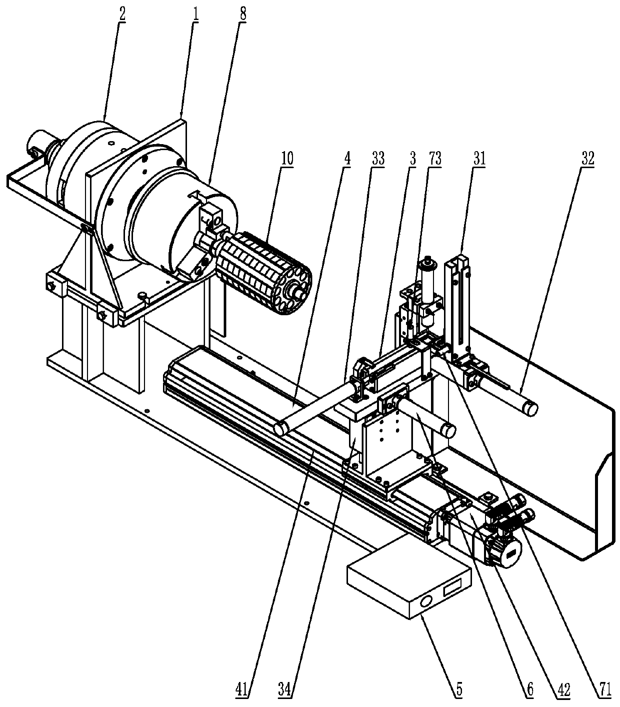
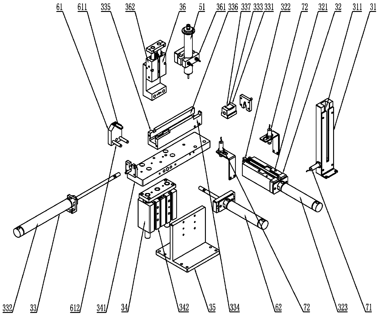
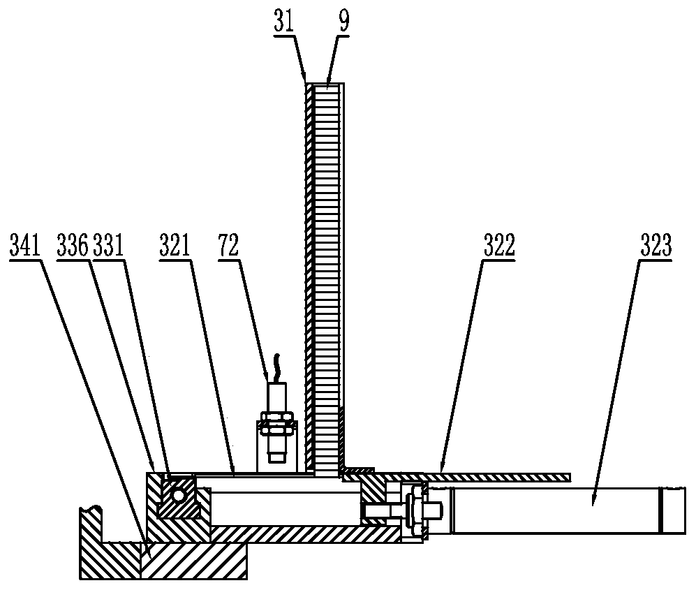
[0030] like Figure 1 to Figure 4 As shown, an automatic surface-mounted magnetic steel equipment includes a motor rotor support structure 1, an angular rotation device 2, a magnetic steel surface-mounted action device 3 and an automatic dispensing device 5, and the angular rotation device 2 can drive the motor rotor 10 in the The motor rotor rotates on the support structure 1, and the angular rotation device 2 includes a power device that provides rotational power, which may specifically be a motor. The magnetic steel surface mount action device 3 includes a storage mechanism 31, a discharge mechanism 32, a first moving mechanism 33 and a lifting and pressing mechanism 34, and the first moving mechanism 33 includes a positioning slider 331 and a positioning slider for driving. Part 331 moves the first power unit 332, the discharge mechanism 32 can take out the magnetic steel from the storage mechanism 31 and send it to the positioning slider 331, and the automatic dispensing ...


PUM


Abstract

The invention discloses an automatic magnetic steel surface mounting device. The automatic magnetic steel surface mounting device comprises a motor rotor supporting structure, an angle rotating device, a magnetic steel surface mounting action device and an automatic dispensing device for spraying glue to magnetic steel, the angle rotating device can drive a motor rotor to rotate on the motor rotorsupporting structure, and the magnetic steel surface mounting action device comprises a storage mechanism, a discharging mechanism, a first moving mechanism and a lifting pressing mechanism. By controlling a high-precision motor, the circumferential rotation angle and the axial displacement of the device are accurate, and the position accuracy of magnetic steel surface mounting is ensured; the problems of glue overflowing, glue shortage and the like are solved; the inconvenience of manual material taking is solved; the magnetic steel is attached from bottom to top, and reliable movement and adhesion of the magnetic steel are guaranteed; the problems of inconvenience of manual operation, high labor intensity and narrow space operability are efficiently solved; and efficiency is improved, and manual labor is reduced.

Description

technical field [0001] The invention relates to a magnetic steel pasting device, in particular to an automatic surface-mounted magnetic steel device. Background technique [0002] The traditional method of pasting magnetic steel on the surface of the motor rotor is manual pasting. This method has low paste efficiency, and it is difficult to accurately control the distance between pasting positions, and the accuracy cannot be guaranteed. Moreover, it is difficult to control the amount of artificial glue, which will cause problems such as lack of glue and glue overflow. The firmness of the magnetic steel and the height consistency after fixing are poor, and the quality is difficult to be guaranteed. In addition, due to the problem of the pasting angle of the magnetic steel, there are problems such as difficulty in pasting in some positions, inconvenient operation, and high labor intensity. Contents of the invention [0003] In view of the above problems, the present inventi...

Claims


Application Information

Patent Timeline
Patent Type & Authority Applications(China)
IPC IPC(8): H02K15/03
CPCH02K15/03
Inventor 于洋杨金明王雪王忠玉迟宁
Owner KEDE NUMERICAL CONTROL CO LTD
Learn More