Control circuit, control method and device of control circuit and air conditioner

A control circuit and control device technology, applied in the direction of output power conversion device, electrical components, AC power input conversion to AC power output, etc., can solve the problem of temperature rise, component damage of frequency conversion main circuit, and affecting frequency conversion main circuit Work stability and other issues to achieve the effect of improving service life, protecting safety, and reducing over-current burnout

Active Publication Date: 2020-02-21
GD MIDEA HEATING & VENTILATING EQUIP CO LTD +1
View PDF16 Cites 1 Cited by
  • Summary
  • Abstract
  • Description
  • Claims
  • Application Information

AI Technical Summary

Problems solved by technology

[0002] In related technical solutions, no matter whether the air conditioner is in the working state or in the standby state, its frequency conversion main circuit is always in the power-on state, and the electrolytic capacitors, voltage equalizing resistors and other devices in the frequency conversion main circuit will generate a certain amount of power consumption and heat. At the same time, the heat in the electronic control chamber will cause the temperature in the electronic control chamber to rise, which will affect the stability of the frequency conversion main circuit. When the surge occurs, it will cause damage to the components of the main circuit of the frequency conversion

Method used


Image

  • Control circuit, control method and device of control circuit and air conditioner
  • Control circuit, control method and device of control circuit and air conditioner
  • Control circuit, control method and device of control circuit and air conditioner

Examples


Embodiment 1

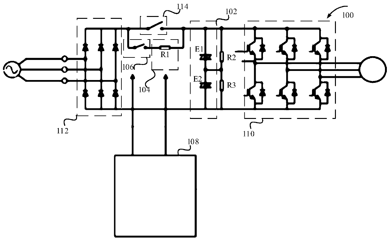
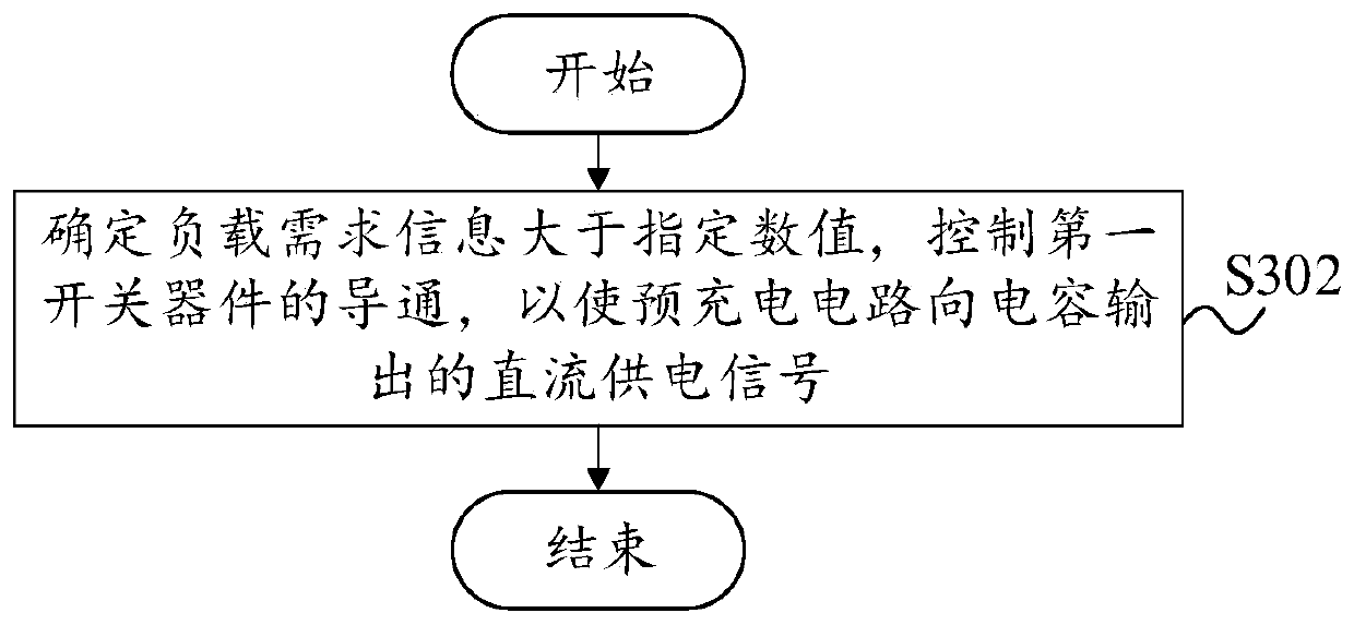
[0057] In one embodiment of the present invention, as figure 1 As shown, the control circuit 100 includes a capacitor 102, the capacitor 102 is configured to supply power to the load; a pre-charging circuit 104, the pre-charging circuit 104 is configured to charge the capacitor 102, the first end of the pre-charging circuit 104 is connected to the bus line, The second end of the pre-charging circuit 104 is connected to the capacitor 102; the first switching device 106, and the first switching device 106 is connected in series between the first end of the pre-charging circuit 104 and the bus line or between the second end of the pre-charging circuit 104 and the bus line. between the capacitors 102; the control device 108, the control device 108 is connected to the control terminal of the first switching device 106, and the control device 108 is configured to control the conduction state of the first switching device 106 according to the load demand information.

[0058] In the ...

Embodiment 2

[0072]In the above embodiment, the control circuit 100 further includes: a second switching device 114, the first end of the second switching device 114 is connected to the bus line, and the second end of the second switching device 114 is connected to the capacitor 102; the control device 108 is also used for: controlling the conduction state of the second switching device 114 according to the comparison result of the bus voltage and the voltage threshold.

[0073] In this embodiment, the control circuit 100 further includes a second switching device 114, wherein the first end of the second switching device 114 is connected to the bus line, and the second end of the second switching device 114 is connected to the capacitor 102, that is The pre-charging circuit 104 connected in series and the first switching device 106 and the second switching device 114 form a parallel relationship, and whether the pre-charging circuit 104 finishes charging the capacitor 102 can be controlled ...

Embodiment 3

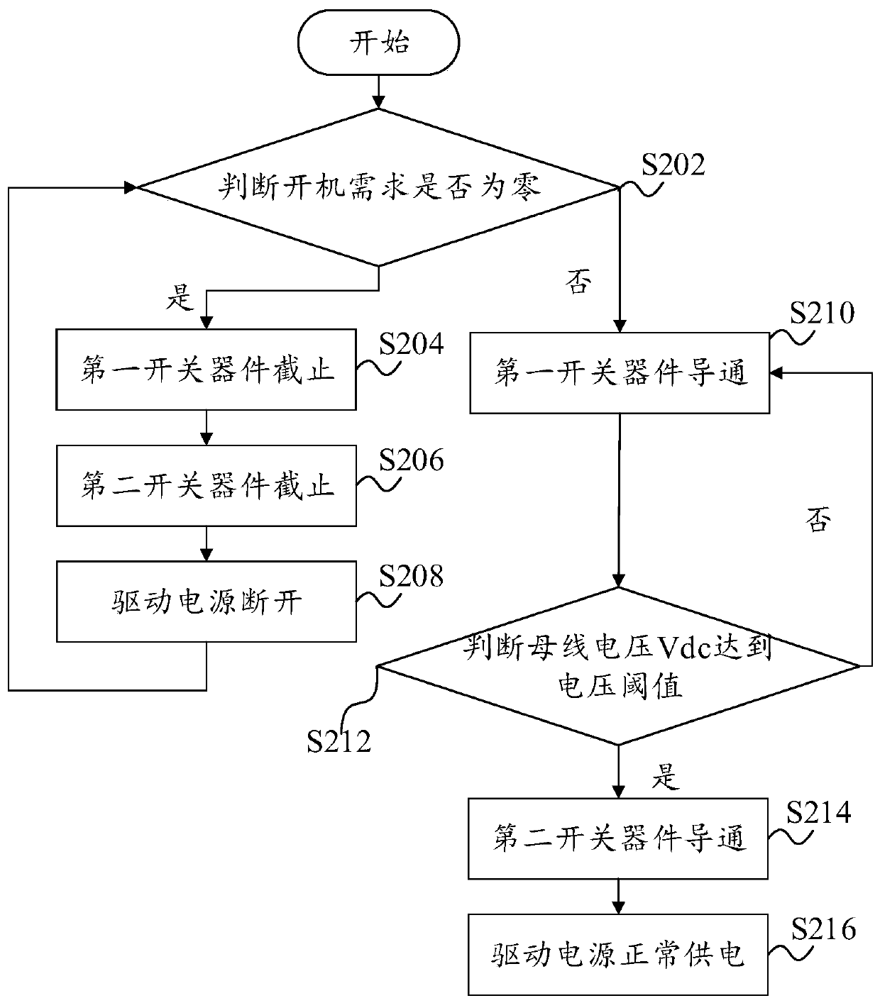
[0076] In any of the above embodiments, taking an air conditioner including an indoor unit and an outdoor unit as an example, the control circuit is arranged in the outdoor unit, and a controller is arranged in the indoor unit, wherein the controller communicates with the control device, and the indoor unit When the outdoor unit is powered by the same driving power supply, combined with figure 1 and figure 2 As shown, the control device 108 installed in the outdoor unit specifically performs the following steps:

[0077] S202, judging whether the power-on demand is zero, if the judgment result is yes, execute S204, and if the judgment result is no, execute S210;

[0078] S204, the first switching device is turned off;

[0079] S206, the second switching device is turned off;

[0080] S208, the driving power is disconnected;

[0081] S210, turning on the first switching device;

[0082] S212, judging that the bus voltage Vdc reaches the voltage threshold, if the judgment ...


PUM


Abstract

The invention provides a control circuit, a control method of the control circuit, a control device of the control circuit and an air conditioner. The control circuit includes: a capacitor, which is configured to supply power to a load; a pre-charging circuit, which is configured to charge the capacitor, wherein the first end of the pre-charging circuit is connected with a bus line, and the secondend of the pre-charging circuit is connected with the capacitor; a first switching device, which is connected in series between the first end of the pre-charging circuit and the bus line or between the second end of the pre-charging circuit and the capacitor; and a control device, which is connected with the control end of the first switching device, wherein the control device is configured to control the conduction state of the first switching device according to load demand information, and control the first switching device to be cut off, that is, the pre-charging circuit stops charging the capacitor, when no load demand exists, so that the circuit where the capacitor is located is not electrified, and the power consumption of the control circuit is reduced.

Description

technical field [0001] The invention relates to the technical field of electric appliance control, in particular to a control circuit, a control method for the control circuit, a control device for the control circuit, and an air conditioner. Background technique [0002] In related technical proposals, whether the air conditioner is in the working state or in the standby state, its frequency conversion main circuit is always powered on, and the electrolytic capacitors, voltage equalizing resistors and other devices in the frequency conversion main circuit will generate a certain amount of power consumption and heat. At the same time, the heat in the electronic control chamber will cause the temperature in the electronic control chamber to rise, which will affect the stability of the frequency conversion main circuit. When the surge occurs, the components of the frequency conversion main circuit will be damaged. Contents of the invention [0003] The present invention aim...

Claims


Application Information

Patent Timeline
Patent Type & Authority Applications(China)
IPC IPC(8): H02M1/36H02M5/458
CPCH02M1/36H02M5/458
Inventor 钱雄吴田刘国峰温永和
Owner GD MIDEA HEATING & VENTILATING EQUIP CO LTD
Why Eureka
Try Eureka