Flat-jet fuel injector for an aircraft turbine engine

A technology of turbine engine and fuel injector, which is applied in the directions of injection device, liquid injection device, burner, etc., can solve the problem of expensive micro-catheter, and achieve the effects of simplifying manufacturing, improving manufacturability, and simplifying manufacturing.

Active Publication Date: 2020-02-21
SAFRAN HELICOPTER ENGINES
View PDF7 Cites 0 Cited by
  • Summary
  • Abstract
  • Description
  • Claims
  • Application Information

AI Technical Summary

Problems solved by technology

Therefore, the assembly of microcatheters is technically delicate and expensive

Method used


Image

  • Flat-jet fuel injector for an aircraft turbine engine
  • Flat-jet fuel injector for an aircraft turbine engine
  • Flat-jet fuel injector for an aircraft turbine engine

Examples


Embodiment Construction

[0032] Figure 1 to Figure 4 What has been described above can of course be used to better understand the invention.

[0033] Figure 5 An environment in which flat jet fuel injector 110 may be used is shown. This is the combustion module of a turbine engine of an aircraft, such as a helicopter, which module includes a combustion chamber 130 .

[0034] A combustion chamber 130 is located within a casing 132 of the turbine engine and includes walls 134 that internally define a combustion space into which a mixture of air and fuel is injected and combusted.

[0035] Fuel is injected into chamber 130 through one or more injectors 110 , here affixed to housing 132 and passing through orifices 136 in wall 134 .

[0036] injector or each injector 110 is figure 1 Types of injectors shown and described above.

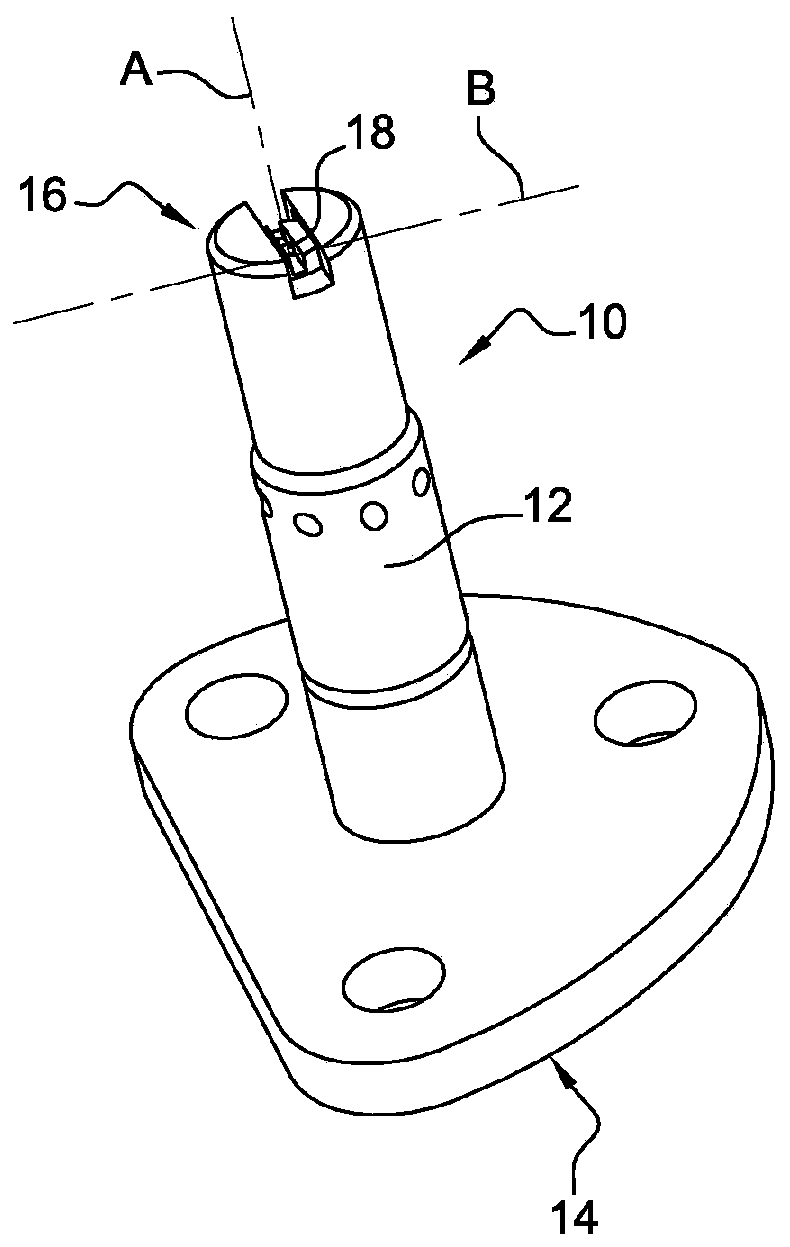
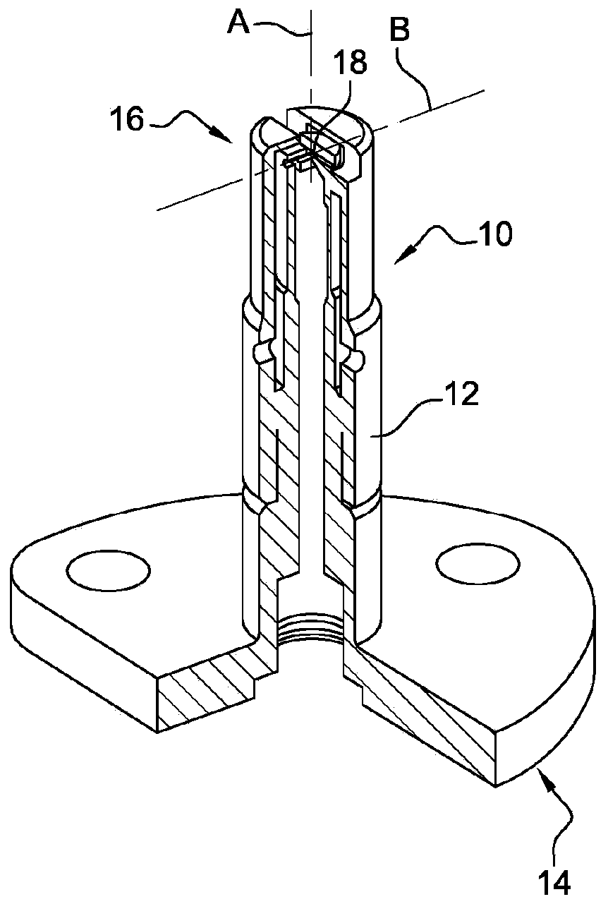
[0037] Figure 6a to Figure 24e Several variant embodiments of injector 110 are shown. The injector 110 comprises a body 112 having a generally elongated shape with an a...


PUM


Abstract

A flat-jet fuel injector for an aircraft turbine engine, comprising a body (112) having a generally elongate shape having a longitudinal axis A, said body comprising a main pipe (118) having a generally elongate shape having a longitudinal axis B substantially perpendicular to said longitudinal axis A, the two longitudinal ends (120) of said main pipe being connected directly and respectively to longitudinal ends of two secondary pipes (119) having a generally elongate shape having a longitudinal axis C at least substantially parallel to said longitudinal axis A, and being configured to form,respectively, two separate fuel flow inlets intended to meet substantially at the middle of said main pipe which comprises at least one ejection slot (124) for ejecting said fuel jet, characterised inthat at least one of said main and secondary pipes defines a flow area, at least one geometric parameter of which, such as the shape or a dimension, varies along said pipe and / or is different from the same geometric parameter defined by a flow area of another of said pipes.

Description

technical field [0001] The present invention relates to flat jet fuel injectors for aircraft turbine engines. Background technique [0002] The background art includes documents FR-A1-2 971 039 and FR-A1-3 013 805 in particular. [0003] A mixture of compressed air and a suitable fuel is typically injected into the combustion chamber of a turbine engine using one or more injectors. The injector is for example fixed to the housing and passes through an orifice in the chamber wall in preparation for injecting fuel into the chamber in the form of flaked fuel droplets. [0004] Flat jet fuel injector 10 (such as Figure 1 to Figure 4 The illustrated flat jet fuel injector) generally includes a body 12 having a generally elongated shape with an axis A of elongation. The body 12 comprises a first longitudinal end 14 for fuel supply and a second longitudinal end 16 for injecting a flat jet of fuel. The second end portion 16 includes a main tube 18 having a generally elongated sh...

Claims


Application Information

Patent Timeline
Patent Type & Authority Applications(China)
IPC IPC(8): F23R3/28F23D11/38
CPCF23R3/28F23D11/38F23R2900/00004Y02T50/60B05B7/025
Inventor 丹尼斯·尚特鲁托马斯·勒德林纪尧姆·莫列斯西蒙·梅洛瑞特
Owner SAFRAN HELICOPTER ENGINES
Why Eureka
Try Eureka