Test system and method for adjusting clock error of intelligent electric meter

A smart meter and clock error technology, which is applied in the field of smart meter clock error adjustment test system, can solve the problem that the clock chip cannot get a high score, and achieve the effects of convenient reference, improved detection efficiency, and fast transmission speed

Pending Publication Date: 2020-02-25
HENGYE ELECTRONICS JIAXING CITY
View PDF0 Cites 4 Cited by
  • Summary
  • Abstract
  • Description
  • Claims
  • Application Information

AI Technical Summary

Problems solved by technology

If the clock error linearity of the clock chip is not very good, it will not be able to get a high score

Method used


Image

  • Test system and method for adjusting clock error of intelligent electric meter
  • Test system and method for adjusting clock error of intelligent electric meter
  • Test system and method for adjusting clock error of intelligent electric meter

Examples


Embodiment 1

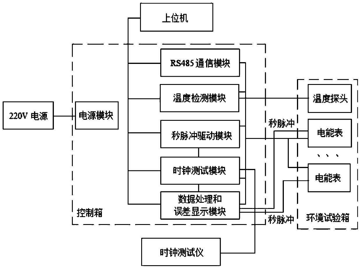
[0041] The smart meter clock error adjustment test system of this embodiment, such as figure 1 As shown, it includes: a host computer, a temperature detection module, a clock test module, a second pulse drive module, a data processing and error display module, a communication module, and a power supply module; the host computer communicates with the temperature detection module, the clock test module, The second pulse drive module, data processing and error display module are connected.

[0042] The power module is used to provide power to the entire system.

[0043] The temperature detection module is used to detect the ambient temperature of the smart meter; wherein, the detection of the ambient temperature of the smart meter is detected by a temperature probe.

[0044] The second pulse drive module is connected with the clock test module, and is used to connect the second pulse output by the smart meter to the clock test module when the ambient temperature of the smart met...

Embodiment 2

[0105] Smart meter clock error adjustment test method, such as Figure 5 shown, including steps:

[0106] S11. The temperature detection module detects the ambient temperature of the smart meter;

[0107] S12. The second pulse drive module connects the second pulse output by the smart meter to the clock test module by detecting the ambient temperature of the smart meter;

[0108] S13. The clock test module receives the pulse output by the second pulse drive module, and tests the error of the clock, and sends the test result to the data processing and error display module;

[0109] S14. The data processing and error display module receives the clock error test result sent by the clock test module, and displays the test result through the host computer.

[0110] In this embodiment, after the step S14, it also includes:

[0111] S15. The data storage module stores the test result of the clock error.

[0112] The ambient temperature of the smart meter detected in the step S11 ...


PUM


Abstract

The invention discloses a test system and method for adjusting a clock error of an intelligent electric meter. According to the test system for adjusting a clock error of an intelligent electric meter, a host computer is connected with a temperature detection module, a clock test module, a second pulse drive module, and a data processing and error display module through a communication module; thetemperature detection module is configured to detect ambient temperature of the intelligent electric meter; the second pulse drive module and the clock test module are configured to connect a secondpulse output by the intelligent electric meter to the clock test module when the ambient temperature of the intelligent electric meter is detected; the clock test module is connected to the data processing and error display module, and is configured to receive the pulse output by the second pulse drive module, test the clock error, and send the test result to the data processing and error displaymodule; and the data processing and error display module is configured to receive the test result of the clock error sent by the clock test module, and display the test result through the host computer.

Description

technical field [0001] The invention relates to the technical field of smart meters, in particular to a clock error adjustment test system and method for smart meters. Background technique [0002] As an instrument for measuring electric energy, the electric energy meter is also called an electric meter, a fire meter, an electric energy meter, and a kilowatt-hour meter. Strict requirements, especially in the cost control function and time-sharing measurement, have higher requirements for the accuracy of the clock, so the daily timing error of the electric energy meter must be strictly tested before leaving the factory, so that the time-sharing of the electric energy meter Metering performance meets the requirements. The accuracy of the daily timing error depends on the clock chip of the electric energy meter or the internal clock module of the single-chip microcomputer. In order to achieve the accuracy of the clock, temperature compensation is often used. Its initial clock...

Claims


Application Information

Patent Timeline
Patent Type & Authority Applications(China)
IPC IPC(8): G01R35/04G04G5/00
CPCG01R35/04G04G5/00
Inventor 洪晨力马巧娟胡萌王勤龙
Owner HENGYE ELECTRONICS JIAXING CITY
Why Eureka
Try Eureka