Expandable power distribution cabinet utilizing pulley lifting principle

A technology of power distribution cabinets and pulleys, applied in the direction of electrical components, substation/switch layout details, etc., can solve problems such as troublesome installation and maintenance of internal electrical components, troublesome maintenance and inspection of internal electrical components, limited internal space of power distribution cabinets, etc., to achieve Convenient maintenance and repair, easy equipment observation, convenient installation and maintenance

Inactive Publication Date: 2020-02-25
程浩
View PDF5 Cites 1 Cited by
  • Summary
  • Abstract
  • Description
  • Claims
  • Application Information

AI Technical Summary

Problems solved by technology

[0003] Due to the complex internal structure of the power distribution cabinet, the volume is too large, and because the internal space of the power distribution cabinet is limited, it is very troublesome for workers to install and maintain the internal electrical components, and it often takes a long time to complete the installation of an electrical component , not only takes a long time to work, reduces work efficiency, but also requires a long time of highly focused viewing, which can easily lead to visual fatigue, which is likely to cause installation errors, and the crowded operating space is also likely to cause installation errors, resulting in certain safety hazards. During the maintenance of internal electrical components, due to the excessive equipment and overcrowded concentration, it also brings certain troubles to the maintenance and inspection of internal electrical components, and the operation is very troublesome

Method used


Image

  • Expandable power distribution cabinet utilizing pulley lifting principle
  • Expandable power distribution cabinet utilizing pulley lifting principle
  • Expandable power distribution cabinet utilizing pulley lifting principle

Examples


Embodiment Construction

[0031] The following will clearly and completely describe the technical solutions in the embodiments of the present invention with reference to the accompanying drawings in the embodiments of the present invention. Obviously, the described embodiments are only some, not all, embodiments of the present invention. Based on the embodiments of the present invention, all other embodiments obtained by persons of ordinary skill in the art without making creative efforts belong to the protection scope of the present invention.

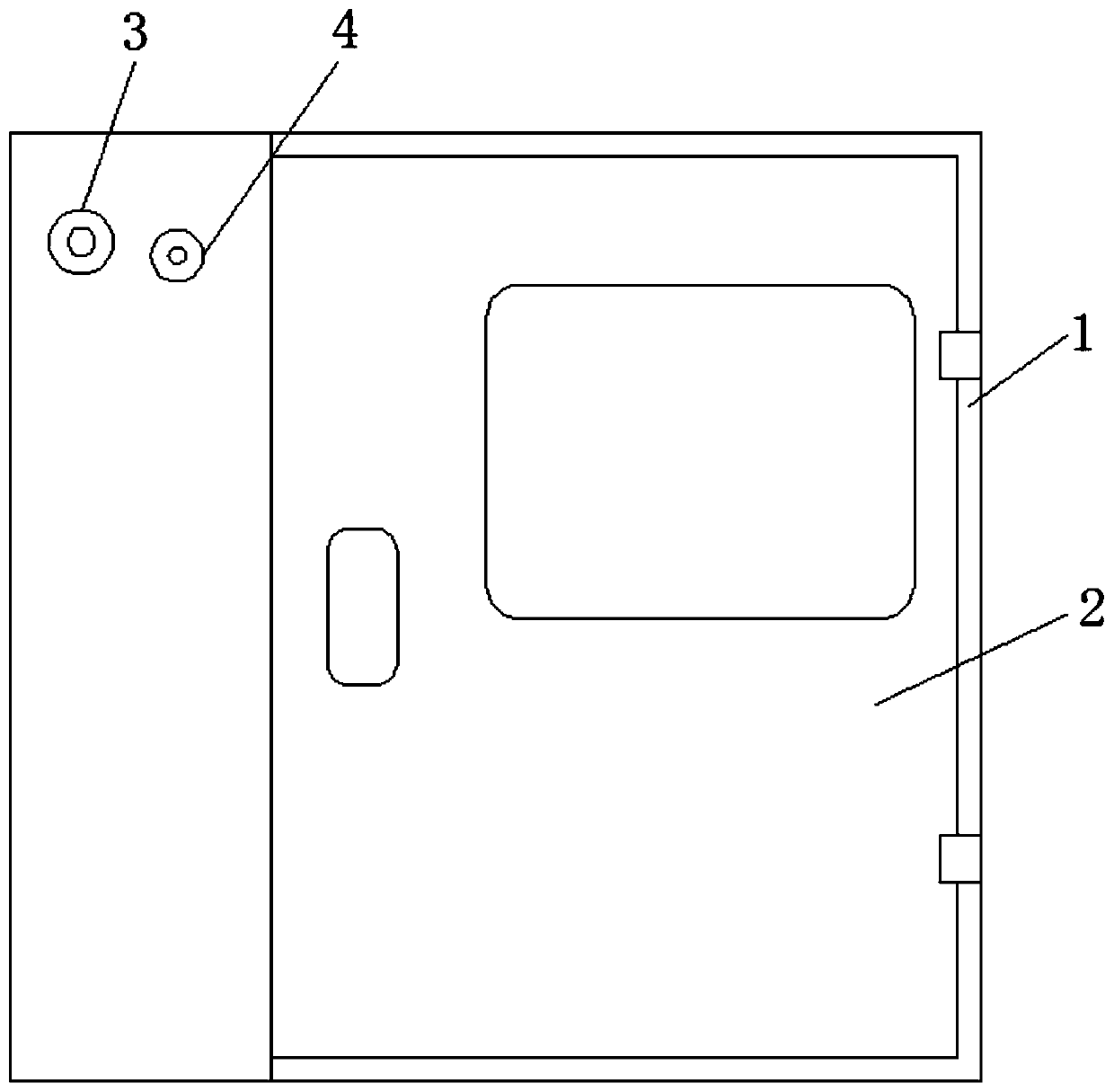
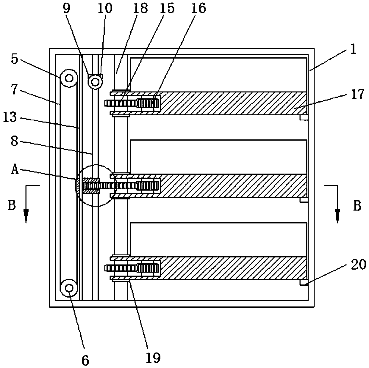
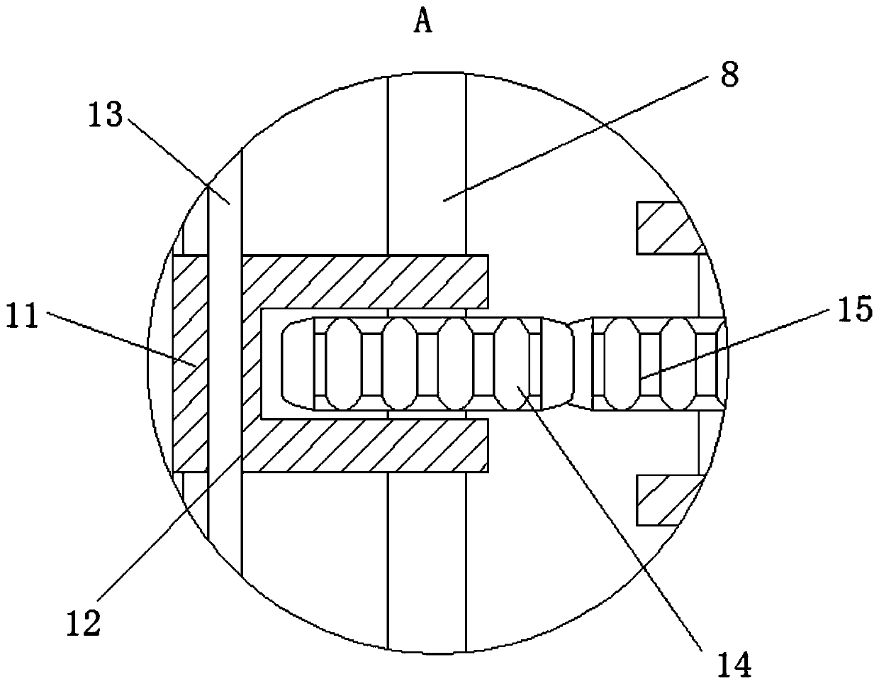
[0032] see Figure 1-7 , an expandable power distribution cabinet using the principle of pulley lifting, including a cabinet body 1, a cabinet door 2, a height adjustment button 3, an expansion adjustment button 4, a driving pulley 5, a driven pulley 6, a conveyor belt 7, a rotating rod 8, and a fixed gear 9. Adjusting gear 10, lifting slider 11, limit hole 12, guide rod 13, first expansion gear 14, second expansion gear 15, third expansion gear 16, equipment ...


PUM


Abstract

The invention relates to the technical field of power distribution cabinets, and discloses an expandable power distribution cabinet utilizing a pulley lifting principle, which comprises a cabinet body. A cabinet door is hinged to the exterior of the cabinet body; the exterior of the cabinet body is movably connected with a height adjusting button and an unfolding adjusting button; a driving pulleyand a driven pulley are fixedly connected to the interior of the cabinet body; the exteriors of the driving pulley and the driven pulley are movably connected with a conveying belt; a rotating rod ismovably connected to the interior of the cabinet body; a fixed gear is fixedly connected to the outer part of the rotating rod. Through matched use among the driving pulley, the driven pulley, the conveying belt and a lifting sliding block, the effect of adjusting the lifting sliding block is achieved, a first unfolding gear is conveniently adjusted to be engaged with different second unfolding gears, the effect of unfolding different equipment mounting plates is achieved, and electrical elements on the different equipment mounting plates are conveniently mounted and maintained.

Description

technical field [0001] The invention relates to the technical field of power distribution cabinets, in particular to an expandable power distribution cabinet using the lifting principle of pulleys. Background technique [0002] The power distribution cabinet is the general name of the electrical equipment control center. The power distribution cabinet is used in the occasions where the load is relatively scattered and there are few circuits; the motor control center is used in the occasions where the load is concentrated and there are many circuits. The electrical energy of the circuit is distributed to the nearest loads, and this level of equipment should provide protection, monitoring and control for the loads. [0003] Due to the complex internal structure of the power distribution cabinet, the volume is too large, and because the internal space of the power distribution cabinet is limited, it is very troublesome for workers to install and maintain the internal electrical...

Claims


Application Information

Patent Timeline
Patent Type & Authority Applications(China)
IPC IPC(8): H02B1/34H02B1/36
CPCH02B1/34H02B1/36
Inventor 程浩
Owner 程浩
Why Eureka
Try Eureka