Supercharge Your Innovation With Domain-Expert AI Agents!

Two-wire system communication circuit

A communication circuit and two-wire system technology, which is applied in the direction of line transmission parts, electrical components, transmission noise suppression, etc., can solve the problems of application restrictions, easy connection errors, and decreased accuracy of communication data.

Active Publication Date: 2020-02-25
SHENZHEN MCQUAY AIR CONDITIONING
View PDF12 Cites 1 Cited by
  • Summary
  • Abstract
  • Description
  • Claims
  • Application Information

AI Technical Summary

Problems solved by technology

[0002] At present, the communication between the main control board of the air conditioner and the wire controller mostly uses a four-wire system, that is, two power lines and two communication lines. This communication method has high wire costs and has strict requirements on the line sequence, and it is easy to connect incorrectly and cause failure; Therefore, R&D personnel superimposed communication signals on two power lines to realize two-wire communication and non-polarity wiring, as shown in patents CN 207852079U and CN106326174A
[0003] However, in these two patents, both sides of the communication transmit the data “0” and “1” through the voltage amplitude. The disadvantage of this method is that there may be various interference voltages on the communication line, and the communication data is easily disturbed. , resulting in a decline in the accuracy of communication data, and the communication distance is relatively short, and the application is limited

Method used


Image

  • Two-wire system communication circuit
  • Two-wire system communication circuit
  • Two-wire system communication circuit

Examples


Embodiment Construction

[0027] The following will clearly and completely describe the technical solutions in the embodiments of the present invention with reference to the accompanying drawings in the embodiments of the present invention. Obviously, the described embodiments are only some, not all, embodiments of the present invention. Based on the embodiments of the present invention, all other embodiments obtained by persons of ordinary skill in the art without making creative efforts belong to the protection scope of the present invention.

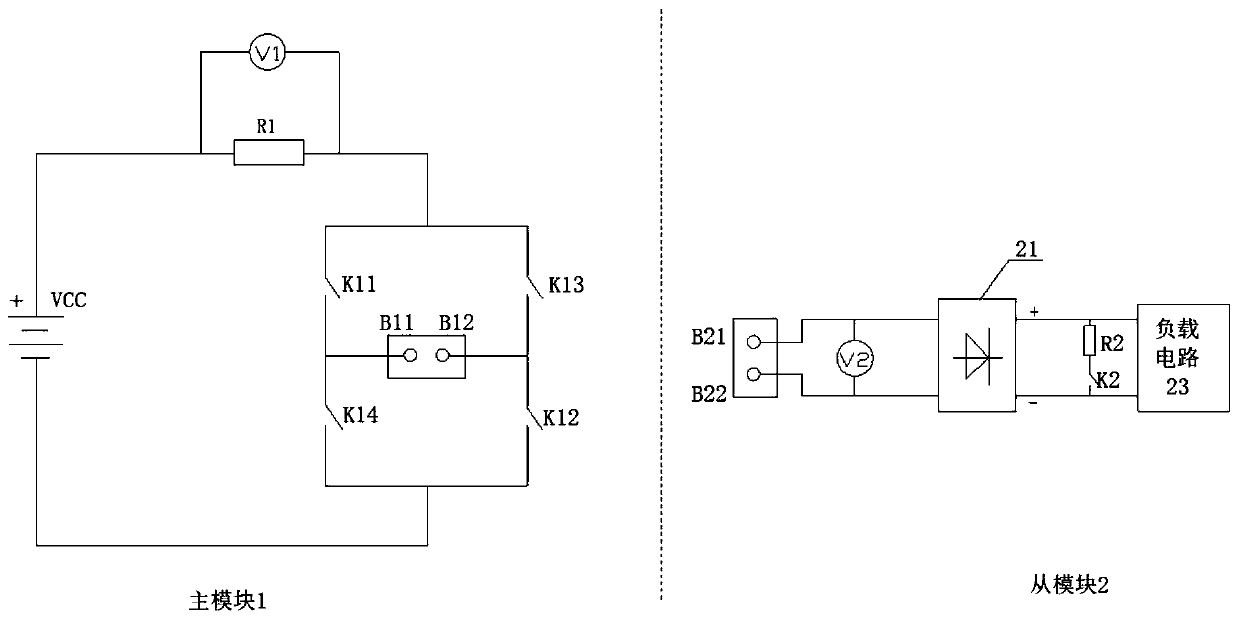
[0028] At present, the communication between the main control board of the air conditioner and the wire controller mostly uses a four-wire system, that is, two power lines and two communication lines. This communication method has high wire costs and has strict requirements on the line sequence, and it is easy to connect incorrectly and cause failure; Therefore, R&D personnel superimpose communication signals on two power lines to realize two-wire communication...


PUM


Abstract

The invention discloses a two-wire system communication circuit, which comprises a master module and a slave module, and is characterized in that the master module comprises a power supply, a samplingresistor, a voltage detection circuit connected with the sampling resistor in parallel, and an H-bridge circuit of which the current input end is connected with the power supply and the sampling resistor to form a current loop; two midpoints of the H-bridge circuit are used as two main binding posts of the main module; the slave module comprises a voltage polarity detection circuit of which the two ends are respectively connected with the two slave binding posts, a rectification circuit of which the input end is respectively connected with the two slave binding posts, an action circuit of which the two ends are respectively connected with the output end of the rectification circuit, and a load circuit of which the input end is respectively connected with the two ends of the action circuit; the action circuit comprises an action resistor and an action switch which are connected in series; the master binding post is connected with the slave binding post. According to the invention, stable, reliable and anti-interference two-line communication is realized, the accuracy is high, and the communication distance is longer; and meanwhile, the main module supplies power to the load circuitthrough the two communication lines, so that the line operation cost is obviously reduced.

Description

technical field [0001] The invention relates to the communication field, in particular to a two-wire communication circuit. Background technique [0002] At present, the communication between the main control board of the air conditioner and the wire controller mostly uses a four-wire system, that is, two power lines and two communication lines. This communication method has high wire costs and has strict requirements on the line sequence, and it is easy to connect incorrectly and cause failure; Therefore, R&D personnel superimposed communication signals on two power lines to realize two-wire communication and non-polarity wiring, as shown in patents CN 207852079U and CN106326174A. [0003] However, in these two patents, both sides of the communication transmit data "0" and "1" through the voltage amplitude. The disadvantage of this method is that there may be various interference voltages on the communication line, and the communication data is easily disturbed. , resultin...

Claims


Application Information

Patent Timeline
IPC IPC(8): H04B3/54H04B3/04H04B15/00
CPCH04B3/54H04B3/04H04B15/00
Inventor 孙建峰谭善兵雷勇
Owner SHENZHEN MCQUAY AIR CONDITIONING
Features
  • R&D
  • Intellectual Property
  • Life Sciences
  • Materials
  • Tech Scout
  • Unparalleled Data Quality
  • Higher Quality Content
  • 60% Fewer Hallucinations
Learn More