Invisible correcting device and method for enhancing retention force thereof

An invisible aligner and retention technology, applied in the field of dental instruments, can solve the problems of increasing the difficulty of brushing teeth for patients, difficult to put into practice in large quantities, and cumbersome bonding steps, etc.

Pending Publication Date: 2020-02-28
深圳爱舒笑科技有限公司
View PDF1 Cites 1 Cited by
  • Summary
  • Abstract
  • Description
  • Claims
  • Application Information

AI Technical Summary

Problems solved by technology

However, not only the bonding steps of the attachment are cumbersome, which increases the work intensity of the doctor, but also the surrounding area of ​​the attachment is not easy to clean, which increases the difficulty of brushing the patient's teeth
China Patent Authorization Announcement No. CN209048324U, announcement date July 20, 2019, the utility model named "a double-layer floating-point invisible appliance without attachments and brackets" embodies another kind of enhanc...

Method used


Image

  • Invisible correcting device and method for enhancing retention force thereof
  • Invisible correcting device and method for enhancing retention force thereof
  • Invisible correcting device and method for enhancing retention force thereof

Examples


Embodiment 1

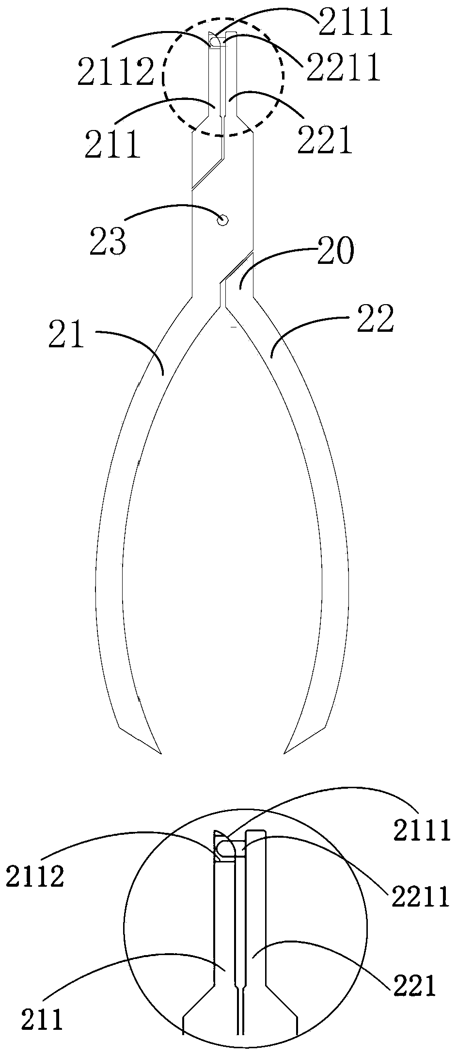
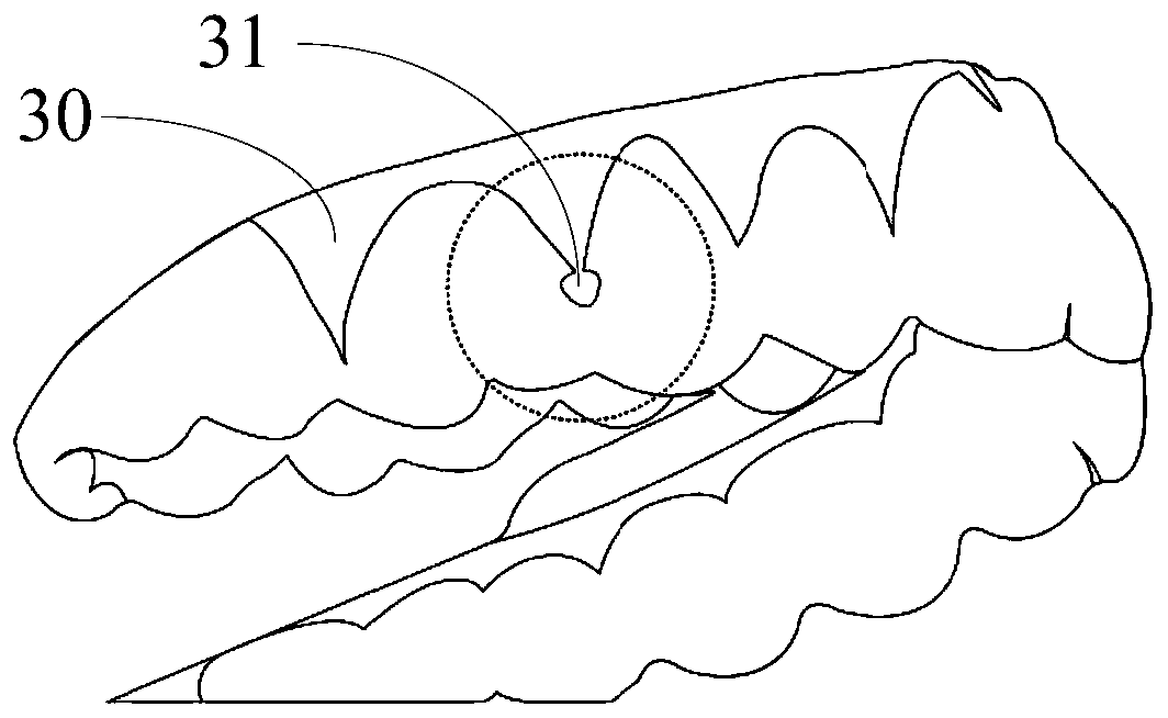
[0033] see Figure 1 to Figure 4 As shown, the present application provides a method for enhancing the retaining force of the clear aligner. The method uses interproximal forceps 20 to form bumps 31 on the clear aligner 30 .

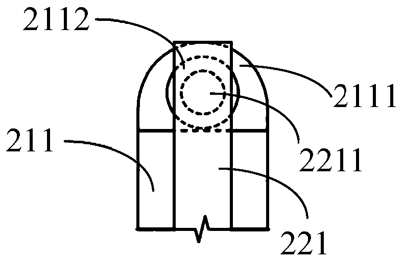
[0034] Specifically, the interproximal forceps 20 includes a first handle 21 , a second handle 22 and a fixed shaft 23 connecting the first handle 21 and the second handle 22 . The top ends of the first handle 21 and the second handle 22 are respectively provided with a first beak 211 and a second beak 221 . The side end of the first pliers beak 211 is provided with a groove 2111 and a circular hole 2112 in the groove 2111; the second pliers beak 221 is provided with a roughly spherical The protrusion 2211 , the end of the protrusion 2211 can be accommodated in the circular hole 2112 of the first beak 211 , that is, the diameter of the protrusion 2211 is smaller than the diameter of the circular hole 2112 of the first beak 211 . The interdental forceps...

Embodiment 2

[0046] see Figure 5 to Figure 9 As shown, the present application also provides a method for enhancing the retaining force of the invisible aligner, using dental surface pliers 40 to form convex points 31 on the invisible aligner 30 .

[0047] The dental face pliers 40 include a first handle 41 , a second handle 42 and a fixed shaft 43 connecting the first handle 41 and the second handle 42 . The top ends of the first handle 41 and the second handle 42 are respectively provided with a first pliers beak 411 and a second pliers beak 421, the first pliers beak 411 protrudes outward with a slight arc, and a round hole 4112 is opened at the side end The second pliers beak 421 is provided with a protrusion 4211 corresponding to the round hole 4112 of the first pliers beak 411, and the end of the protrusion 4211 can be accommodated in the round hole 4112 of the first pliers beak 411. The tooth surface pliers 40 The protruding point 31 protruding to the inner surface is formed on th...


PUM


Abstract

The invention provides a method for enhancing retention force of an invisible correcting device. According to different needs of patients, corresponding forceps can be selected to form convex points protruding to the inner surface at tooth gaps or tooth faces of the invisible correcting device. If the aim is to only increase the retention force so as to control ability of the invisible correctingdevice to a whole tooth, tooth gap forceps are selected to form the convex points protruding to the inner surface at tooth gaps or tooth faces of the invisible correcting device; if the aim is to enhancing the retention force so as to better realize small-amplitude inclined movement, rotation and root-controlled movement of the tooth to a certain specific direction, tooth face forceps are selectedto form the convex points protruding to the inner surface at corresponding positions of the tooth faces of the invisible correcting device. The invention further provides the invisible correcting device which is simple and reliable and has no impact on tooth cleaning.

Description

technical field [0001] The application relates to the field of dental instruments, in particular to a method for enhancing the retention force of an invisible aligner and the invisible aligner. Background technique [0002] The principle of the invisible appliance is to image the dental model in three dimensions, formulate a treatment plan according to the doctor's design, perform three-dimensional image processing and fine tooth position adjustment on the computer, and further reflect each step of the tooth position change to the computer-aided production. On the transparent braces, the misaligned teeth can be corrected by continuously moving the teeth in a small range by wearing a series of braces. The ability of the invisible appliance to move the teeth is closely related to the retention force of the invisible appliance. At present, clinically, the method of bonding accessories on the tooth surface is mainly used, including cleaning the tooth surface, acid-etching the to...

Claims


Application Information

Patent Timeline
IPC IPC(8): A61C7/04A61C7/20
CPCA61C7/04A61C7/20
Inventor 付益慧付益驰
Owner 深圳爱舒笑科技有限公司
Why Eureka
Try Eureka