Odor removing device for clothing manufacture

A technology of fixing frame and fixing shell, applied in the field of garment processing, can solve the problems of slow deodorization rate and low deodorization efficiency, and achieve the effects of improving effectiveness, increasing deodorizing rate and improving work efficiency.

Inactive Publication Date: 2020-02-28
天门市佑琪制衣有限公司
View PDF0 Cites 0 Cited by
  • Summary
  • Abstract
  • Description
  • Claims
  • Application Information

AI Technical Summary

Problems solved by technology

[0003] In the prior art, the clothes are generally stacked or spread out to allow natural ventilation or mechanical ventilation to lose the peculiar smell attached to the clothes, so as to realize the deodorization of the clothes, but the dyes or other materials containing peculiar smells are often attached to the inside of the clothes. It is difficult to quickly bring out odors through air circulation for deodorization operations, making the actual deodorization rate slow and the deodorization efficiency low

Method used


Image

  • Odor removing device for clothing manufacture
  • Odor removing device for clothing manufacture
  • Odor removing device for clothing manufacture

Examples


Embodiment 1

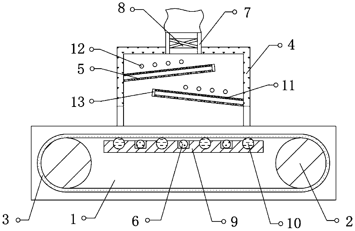
[0022] refer to figure 1 , a deodorizing device for clothing, comprising a fixed frame 1, a drive roller 2 is rotatably connected to both sides between the inner walls at both ends of the fixed frame 1, and a transmission mesh belt 3 is connected to the outer walls of the two drive rollers 2 , the top outer wall of the fixed frame 1 is fixed with a fixed housing 4 of box-like structure, and the bottom ends of both sides of the fixed housing 4 are provided with through grooves, and the inner walls of both sides of the fixed housing 4 are fixed with filter screen plates 5, An exhaust duct 7 is fixed on the top of the fixed housing 4, and an exhaust fan 8 is fixed inside the exhaust duct 7, and a plurality of heating elements 6 are fixed below the conveyor belt 3 between the inner walls at both ends of the fixed frame 1.

[0023] In the present invention, the two filter screen plates 5 are arranged to be inclined, and the inclination direction of the two filter screen plates 5 is...

Embodiment 2

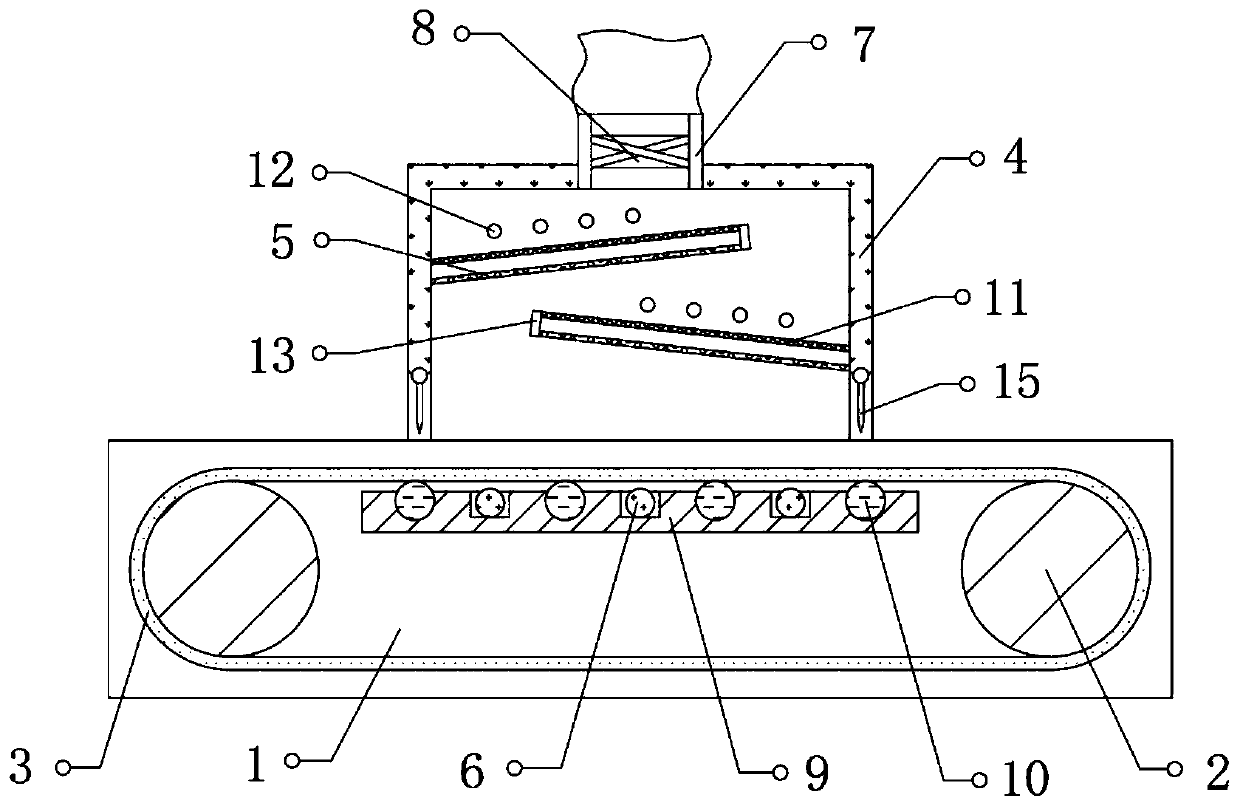
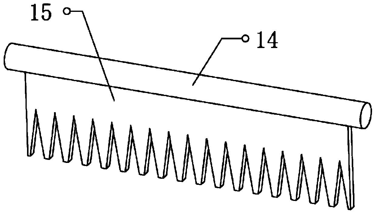
[0028] refer to Figure 2-3 , a deodorizing device for clothing, the top inner wall of the groove is rotatably connected with a fixed rod 14, and the bottom of the fixed rod 14 is fixed with a push plate 15, and one end of the fixed rod 14 is connected with a drive motor, and the bottom of the push plate 15 There are alveoli with a zigzag structure.

[0029] Working principle: Use the drive motor to make the fixed rod 14 and the push plate 15 cyclically swing at the position of the slot, so as to assist in sending the clothes that are blocked at the slot due to folding into or out of the fixed housing 4, so as to avoid the pile of clothes being blocked in the slot. location to improve the effectiveness of the device in actual use.


PUM


Abstract

The invention discloses an odor removing device for clothing manufacture. The odor removing device comprises a fixing frame, driving rollers are rotationally connected to the two sides between the inner walls of the two ends of the fixing frame, a conveying mesh belt is in transmission connection between the outer walls of the two driving rollers, and a fixing shell of a box-shaped structure is fixed to the outer wall of the top of the fixing frame; and penetrating grooves are formed in the bottom ends of the two sides of the fixing shell correspondingly, filter screen plates are fixed to theinner walls of the two sides of the fixing shell correspondingly, an exhaust pipe is fixed to the top of the fixing shell, an exhaust fan is fixed into the exhaust pipe, and a plurality of heating pieces are fixed to the positions, located below the conveying mesh belt, between the inner walls of the two ends of the fixing frame. The conveying mesh belt and clothes materials above the conveying mesh belt are heated through the heating pieces, molecules of peculiar smell gases are active through heating and rise rapidly along with temperature rising, and therefore odor removing operation can beconveniently and rapidly conducted through the exhaust fan, the odor removing speed of the clothes materials is increased, and the working efficiency is improved.

Description

technical field [0001] The invention relates to the technical field of garment processing, in particular to a deodorizing device for garment making. Background technique [0002] Clothing processing used to refer to the textile, sewing and other work done by women, and refers to a kind of physical labor performed by female workers engaged in textile, sewing, embroidery and other work. In today's sense, it refers to modern processing methods and modern machine processing It is a clothing production method mainly supplemented by manual processing. In the process of clothing processing, the cloth is made into clothing after multiple treatments. In the actual clothing making process, the clothing material will be contaminated with paint and other materials, resulting in a large amount of peculiar smell. , It is often necessary to deal with the odor of the clothing. [0003] In the prior art, the clothes are generally stacked or spread out to allow natural ventilation or mechani...

Claims


Application Information

Patent Timeline
Patent Type & Authority Applications(China)
IPC IPC(8): B01D53/74B01D46/12B01D53/86B01D46/00
CPCB01D46/0036B01D46/12B01D53/74B01D53/86B01D2255/802
Inventor 张晓林
Owner 天门市佑琪制衣有限公司
Why Eureka
Try Eureka