Automatic oiling device for automobile brake component assembling

A technology for component assembly and automobile braking, applied in the direction of injection devices, etc.

Inactive Publication Date: 2020-02-28
WEST ANHUI UNIV
View PDF6 Cites 10 Cited by
  • Summary
  • Abstract
  • Description
  • Claims
  • Application Information

AI Technical Summary

Problems solved by technology

[0003] Chinese patent (notification number: CN208503906U) discloses an automatic oiling device for assembly of automobile brake parts, including a base, a split shell, a positioning inner shell, an oil outlet, an oil storage chamber, a pressure oil proximity switch, and a An oiling mechanism for applying lubricating oil to workpieces with different cross-sections. The split shell is sleeved on the base, the positioning inner shell is installed in the inner cavity of the split shell through a plurality of sealing rings, and t

Method used


Image

  • Automatic oiling device for automobile brake component assembling
  • Automatic oiling device for automobile brake component assembling
  • Automatic oiling device for automobile brake component assembling

Examples


Embodiment 1

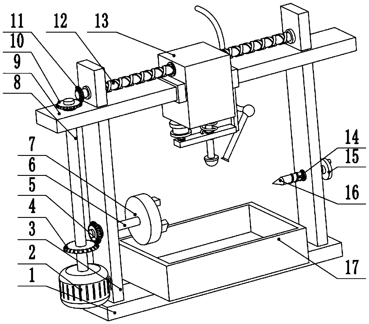
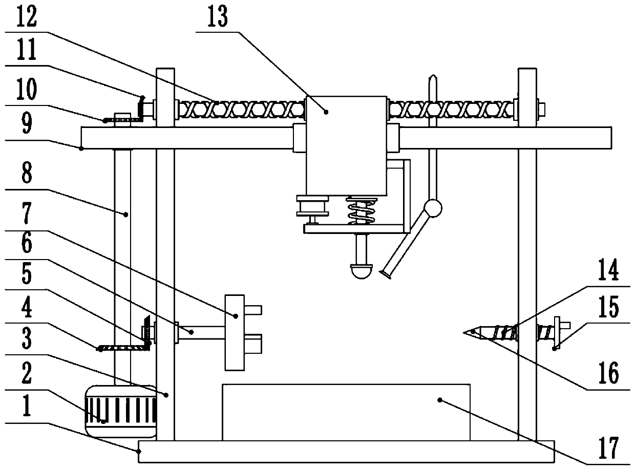
[0025] see Figure 1-3 , an automatic oiling device for assembly of automobile brake parts, comprising a base plate 1, an oil storage tank 17 is provided in the middle of the base plate 1, side plates 3 are provided on the left and right sides of the base plate 1, and the upper part of the side plate 3 is fixedly connected to the top plate 9, left The bottom of the side plate 3 is provided with a driving motor 2, the output shaft of the driving motor 2 is fixedly connected to the rotating shaft 8, the bottom of the rotating shaft 8 is provided with a first bevel gear 4, and the first bevel gear 4 is meshed with the second bevel gear 5, The second bevel gear 5 is fixedly connected to the left end of the rotating rod 6, the middle part of the rotating rod 6 is connected to the side plate 3 on the left side in rotation, and the right end of the rotating rod 6 is provided with a fixed seat 7, and the fixed seat 7 can adopt a three-catch chuck to ensure that the workpiece can be sta...

Embodiment 2

[0028] The other content of this embodiment is the same as that of Embodiment 1, the difference is that: the bottom of the side plate 3 on the right is connected to the threaded rod 14 by rotation, the left side of the threaded rod 14 is provided with a plug 16, and the right side of the threaded rod 14 is provided with a Hand wheel 15, the center of rotation of threaded rod 14 is concentric with the center of rotation of turning rod 6. Because the fixed seat 7 can only fix one end of the workpiece, and when the fixed seat 7 drives the workpiece to rotate, the right end of the workpiece may shake. 16. Press the plug 16 tightly on the right end of the workpiece through the threaded rod 14, so as to play a certain supporting role for the workpiece. Prevent the workpiece from shaking during rotation.

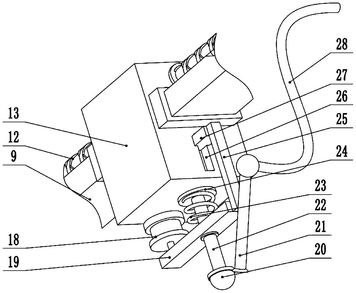
[0029] In the implementation process of the present invention, at first the left end of the workpiece is fixed in the fixed seat 7, and the oil pipe 28 is connected with the oil s...


PUM


Abstract

The invention relates to the technical field of automobile assembling, and discloses an automatic oiling device for automobile brake component assembling. The device comprises a bottom plate, side plates are arranged on the left side and the right side of the bottom plate, the upper parts of the side plates are fixedly connected with a top plate, a driving motor is arranged at the bottom of the side plate on the left side, an output shaft of the driving motor is fixedly connected with a rotating shaft, a first bevel gear is arranged at the lower part of the rotating shaft, the first bevel gearis in meshed connection with a second bevel gear, the second bevel gear is fixedly connected with the left end of a rotating rod, the right end of the rotating rod is provided with a fixed seat, theupper part of the rotating shaft is provided with a third bevel gear, the third bevel gear is in meshed connection with a fourth bevel gear, the fourth bevel gear is fixedly connected with the left end of a lead screw, and the middle of the lead screw is in threaded connection with a sliding seat. The automatic oiling device is suitable for automobile brake component assembling, a workpiece is driven to rotate through the rotating seat, so that a brush head which moves left and right is driven for oiling the surface of the workpiece, the oiling effect is better, and the oil layer on the surface of the workpiece is more uniform.

Description

technical field [0001] The invention relates to the technical field of automobile assembly, in particular to an automatic oiling device for assembly of automobile brake parts. Background technique [0002] Automobile braking system refers to a series of special devices that exert a certain force on certain parts of the automobile (mainly the wheels) to perform a certain degree of mandatory braking. The function of the braking system is: to make the driving car decelerate or even stop forcibly according to the driver's request; to make the stopped car stably park under various road conditions (including on the slope); to make the car driving downhill The speed remains steady. Therefore, the normal use of the brake parts is very important for the operation of the automobile. In order to ensure that the brake parts can operate normally, it is necessary to carry out oiling work on the surfaces of some brake parts that need to slide relatively. [0003] Chinese patent (notifica...

Claims


Application Information

Patent Timeline
IPC IPC(8): B05B13/02B05B15/00
CPCB05B13/0228B05B13/0278B05B15/00
Inventor 张鹏王洪新曹昌勇
Owner WEST ANHUI UNIV
Why Eureka
Try Eureka