
A Rotary Guide Device Based on Bearing Processing Line

A technology of rotary guidance and bearing processing, applied in metal processing, metal processing equipment, manufacturing tools, etc., can solve the problems of suitable positioning of bearings with different sizes and specifications, complex equipment as a whole, single application, etc., and achieve good discharge and use effect. , reduce complexity, and apply a wide range of effects

Active Publication Date: 2020-12-01
RIZHAO ZHONGSHENG FORGING
View PDF8 Cites 0 Cited by
  • Summary
  • Abstract
  • Description
  • Claims
  • Application Information

AI Technical Summary

Problems solved by technology

[0004] In order to solve the above-mentioned technical problems, the present invention provides a rotary guide device based on the bearing processing line to solve the problem of poor applicability of the rotary guide device, which cannot be used for suitable positioning of bearings of different sizes and specifications, and the application is relatively single , and most of them use multiple cylinders to unload the bearings, resulting in the overall complexity of the equipment and the high cost of the problem

Method used


Image

  • A Rotary Guide Device Based on Bearing Processing Line
  • A Rotary Guide Device Based on Bearing Processing Line
  • A Rotary Guide Device Based on Bearing Processing Line

Examples


Embodiment

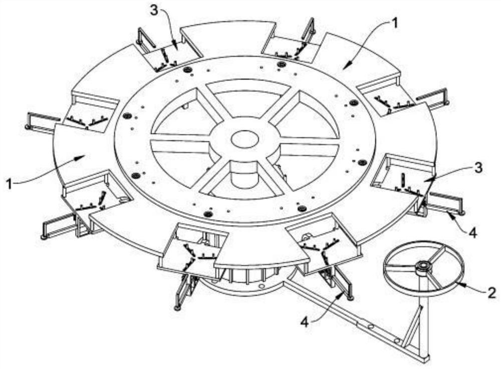
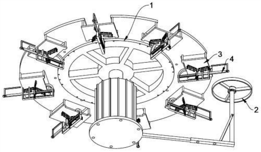
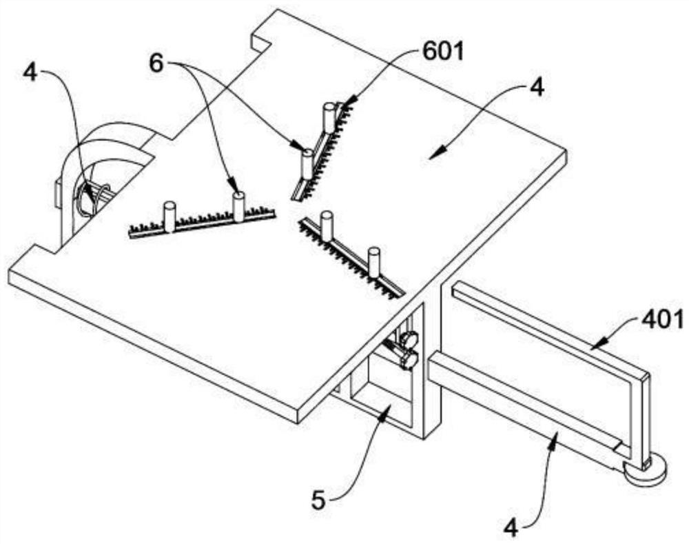
[0031] as attached figure 1 To attach Figure 8 Shown:

[0032] The present invention provides a rotating guiding device based on a bearing processing line, which includes a turntable 1, a top runner 2, and a short positioning shaft 6. The position of the eaves is arranged in a circular array, and eight square gaps are opened through, and a square support plate 3 is supported and suspended under the eight square gaps; a top runner 2 is supported close to the left side of the top runner 2, The top runner 2 is at the same level as the telescopic square rod 4; a mounting frame 5 is supported downward in the middle of the bottom of the supporting plate 3, and the telescopic square rod 4 is inserted through the spring to push through it for installation. The front, middle and rear vertical support connecting rods of the frame 5; the bottom support of the positioning short shaft 6 is welded with a square slide bar, and a total of six positioning short shafts 6 corresponding to the...


PUM


Abstract

The invention provides a rotary guidance device on a bearing based processing line. The rotary guidance device comprises a rotation disk, a top rotation wheel and positioning short shafts, wherein therotation disk integrally sleeves the top end of a rotation shaft of a driving device, eight square gaps are formed in a through manner at the circumferential outer edge of the rotation disk in an annular array, and a square supporting placement plate is supported and hoisted under each of the eight square gaps; the middle part of the bottom of the supporting placement plate downwards supports aninstallation frame, and telescopic square rods are inserted on front, middle and real vertical supporting connecting rods of the installation frame in a through manner through spring pushing; and a square slide rod is supported and welded on the bottom of each of the positioning short shafts, and the six positioning short shafts on inner and outer circles correspondingly sleeve three track rods ina sliding manner. When each of the telescopic square rods is stressed to slide towards the inner side, a semicircular projection block can touch a guide wheel in a pressing slide manner, so a positioning frame can drive the positioning short shafts on the inner and outer circles to slide downwards and hide in three slide grooves in the supporting placement plate. In this way, bearing release is realized, so pressing discharge of a bearing becomes convenient.

Description

technical field [0001] The invention belongs to the technical field of bearing processing supporting equipment, and more specifically relates to a rotating guide device based on a bearing processing assembly line. Background technique [0002] The machining of bearings requires multiple turning processes, such as turning inner holes, turning outer circles, turning chamfers, turning raceways, turning dust-proof grooves, etc. Such cumbersome processes cannot complete all the machining processes of bearing sleeves on a single lathe. Usually, for the production process of the above-mentioned bearing sleeves, multiple equipments are arranged to form a production line for processing. [0003] The last link of the bearing processing production line is generally the application of lubricating butter and the cover installation of the sealing cover ring. Most of the application of lubricating butter and the cover installation of the sealing cover ring are integrated into one process, ...

Claims


Application Information

Patent Timeline
Patent Type & Authority Patents(China)
IPC IPC(8): B23P19/00B65G29/00
CPCB23P19/001B65G29/00
Inventor 卓银杰
Owner RIZHAO ZHONGSHENG FORGING
Learn More