Radial tire mold and making method thereof

A technology for radial tires and tire molds, applied to tires, household appliances, and other household appliances, can solve problems such as waste of resources, unusability, and impact on production efficiency, and achieve the effect of reducing cleaning time and improving work efficiency

Active Publication Date: 2020-02-28
山东力创模具股份有限公司 +1
View PDF3 Cites 0 Cited by
  • Summary
  • Abstract
  • Description
  • Claims
  • Application Information

AI Technical Summary

Problems solved by technology

[0002] At present, tire manufacturing needs to vulcanize the tire through the tire mold. In order to release the air in the mold cavity so that the rubber can be evenly distributed in the mold, the existing tire molds are equipped with Multiple vent holes prevent air holes between the tire blank and the mold during production, resulting in incomplete molding of the formed tire and unusable use, resulting in waste of resources. However, with a set of vent holes, during the vulcanization process, due to the The exhaust in the area is exhausted through circular air holes, which are usually located on the top surface of the inner tube of the mold and penetrated to the outer surface of the mold. Under high pressure and high heat, the unvulcanized raw rubber will be squeezed into the mold Outside the roof cavity; when the air is discharged from the mold, the rubber is squeezed into the drilled vent holes to form rubber hairs, and some of these rubber hairs may be broken in the mold vent holes, which will hinder the discharge of air in the cavity , which in turn causes the rubber to not completely fill the entire mold cavity, in order to avoid this situation, it is necessary to remove the tire mold from the production line for cleaning
The general cleaning operation is to use a drill to drill out the rubber in each air hole, which is very time-consuming and affects production efficiency, so it is urgent to make a radial tire mold and its preparation method

Method used


Image

  • Radial tire mold and making method thereof
  • Radial tire mold and making method thereof
  • Radial tire mold and making method thereof

Examples


Embodiment Construction

[0045] A specific embodiment of the present invention will be described in detail below in conjunction with the accompanying drawings, but it should be understood that the protection scope of the present invention is not limited by the specific embodiment.

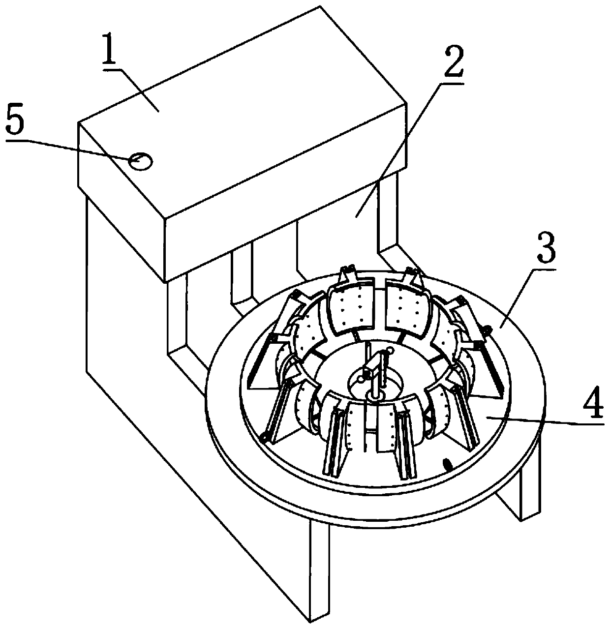
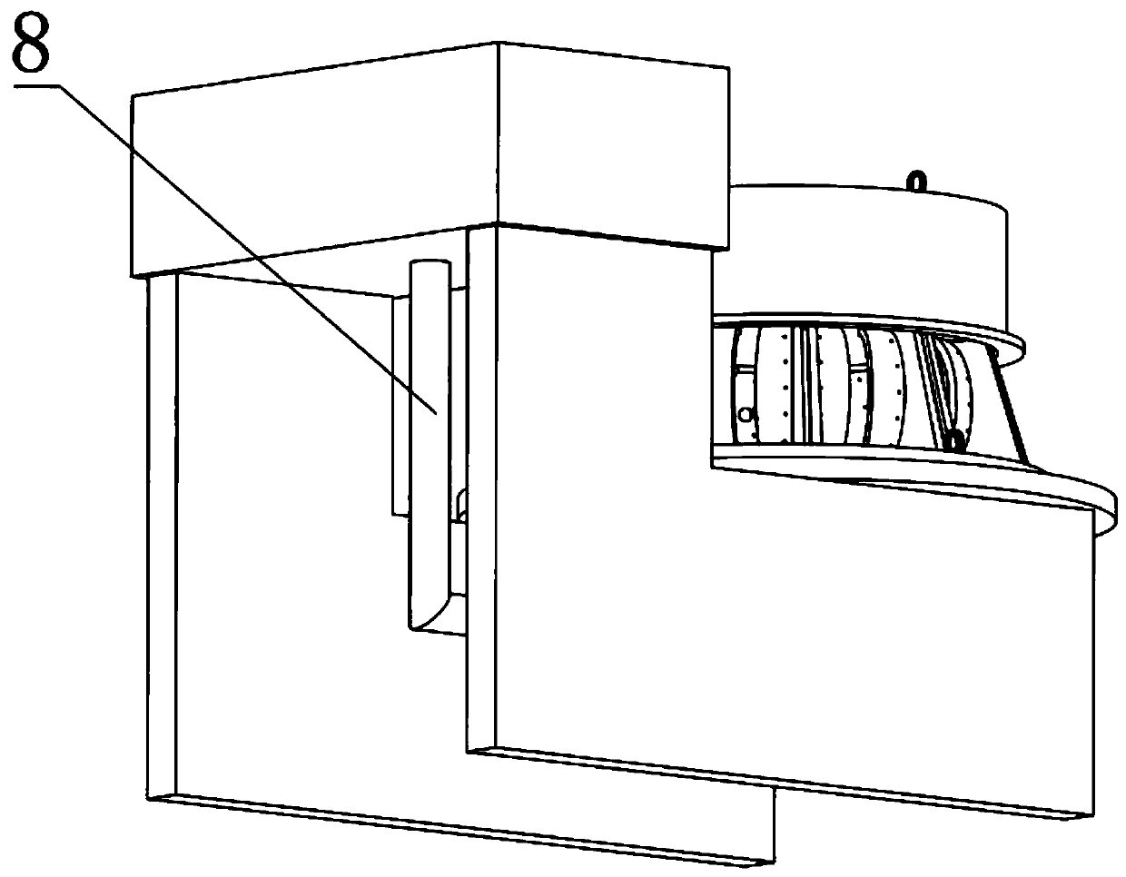
[0046] Such as Figure 1-Figure 16 As shown, the present invention includes two L-shaped plates 2, the upper ends of the vertical plates of the two L-shaped plates 2 are respectively fixedly connected to the middle part of the lower side of the liquid storage tank 1, and the middle part of the upper side of the liquid storage tank 1 is provided with a liquid inlet port 5;

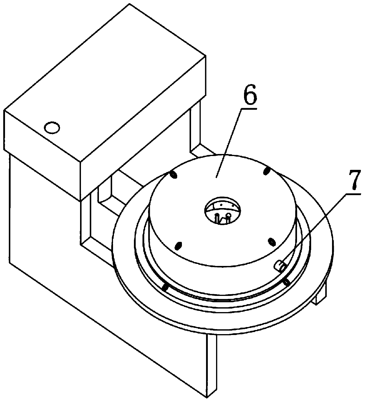
[0047] The middle parts of the upper sides of the two L-shaped plates 2 are respectively fixedly connected to the lower side of the disc 1 3, and the upper side of the disc 1 3 is attached to the lower side of the disc 2 4;

[0048] The middle part of the disc two 4 is provided with a circular through hole one 27, and the upper edge of the two disc two...


PUM


Abstract

The invention discloses a radial tire mold and a making method thereof. The radial tire mold comprises two L-shaped plates and is characterized in that the upper ends of two L-shaped plate vertical plates are fixedly connected with the middle of one end of the lower side of the a liquid storage box correspondingly, a liquid inlet is formed in the middle of one end of the upper side of the liquid storage tank, the middle parts of the upper sides of two L-shaped plate transverse plates are fixedly connected with one end of the lower side of a disc I correspondingly, the upper side of the disc Iis attached to the lower side of a disc II, a circular through hole I is formed in the middle of the disc II, the edge of the upper side of the disc II is fixedly connected with the lower ends of a group of uniformly-arranged lifting rings, the upper side of the disc II is arranged on a group of T-shaped sliding grooves which are radially arranged in a circumferential shape, and one end of one side of one L-shaped transverse plate is fixedly connected with a motor. Residual burrs in vent holes are sucked out through the pressure difference formed between the opposite sides of a group of tire mold blocks and the outer sides of a group of tire mold blocks, each hole does not need to be cleaned by using an electric drill, the cleaning time is reduced, and the working efficiency is improved.

Description

technical field [0001] The invention relates to the field of tire molds, in particular to a radial tire mold and a preparation method thereof. Background technique [0002] At present, tire manufacturing needs to vulcanize the tire through the tire mold. In order to release the air in the mold cavity so that the rubber can be evenly distributed in the mold, the existing tire molds are equipped with Multiple vent holes prevent air holes between the tire blank and the mold during production, resulting in incomplete molding of the formed tire and unusable use, resulting in waste of resources. However, with a set of vent holes, during the vulcanization process, due to the The exhaust in the area is exhausted through circular air holes, which are usually located on the top surface of the inner tube of the mold and penetrated to the outer surface of the mold. Under high pressure and high heat, the unvulcanized raw rubber will be squeezed into the mold Outside the roof cavity; whe...

Claims


Application Information

Patent Timeline
Patent Type & Authority Applications(China)
IPC IPC(8): B29D30/06
CPCB29D30/0606B29D30/0662B29D2030/0607B29D2030/0663
Inventor 李国杰
Owner 山东力创模具股份有限公司
Why Eureka
Try Eureka