Acceleration slip regulation control method and system based on road surface recognition

A road surface recognition and pre-control technology, which is applied in the direction of control drive, control device, electric vehicle, etc., can solve problems such as untimely control, excessive slip rate, and risk of vehicle instability

Active Publication Date: 2020-02-28
的卢技术有限公司
View PDF6 Cites 4 Cited by
  • Summary
  • Abstract
  • Description
  • Claims
  • Application Information

AI Technical Summary

Problems solved by technology

[0005] In view of the above existing problems that the control is not timely or the slip rat

Method used


Image

  • Acceleration slip regulation control method and system based on road surface recognition
  • Acceleration slip regulation control method and system based on road surface recognition
  • Acceleration slip regulation control method and system based on road surface recognition

Examples


Embodiment 1

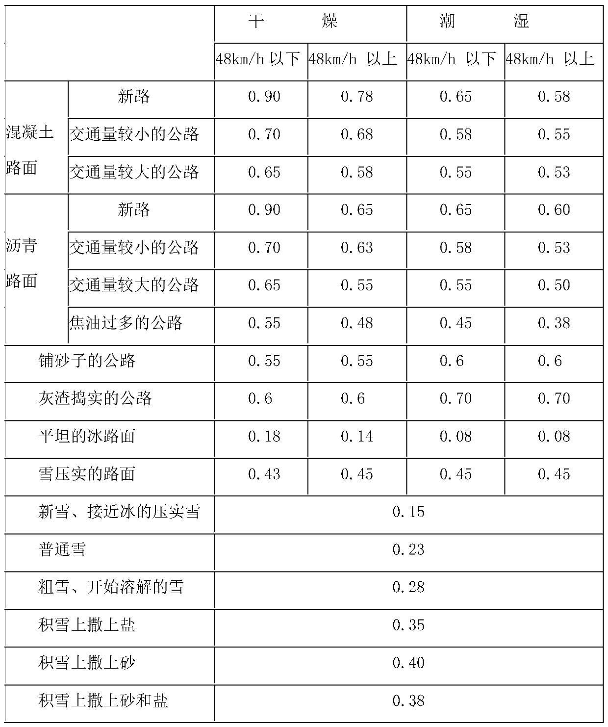
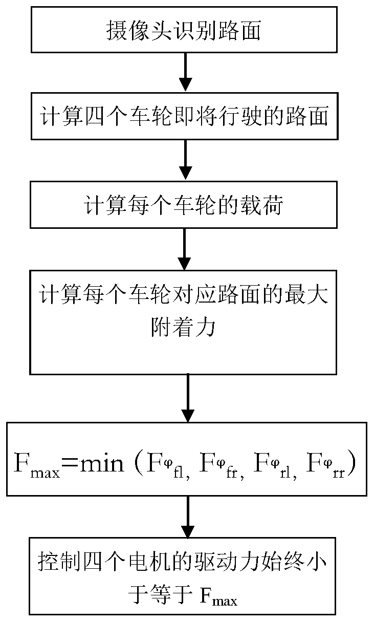
[0035] refer to Figure 1 ~ Figure 4 , which is the first embodiment of the present invention, provides a driving anti-slip pre-control method based on road surface recognition, such as figure 2 , a driving anti-slip pre-control method based on road surface recognition includes: using the camera on the vehicle to detect and identify the road surface; calculating the road surface that the four wheels will drive; using the force sensor to calculate the load of each wheel; using the road surface adhesion coefficient to define the formula and adhesion The coefficient table calculates the maximum adhesion of each wheel corresponding to the road surface The maximum value of the driving force obtained for each wheel is Control the driving forces of the four motors to be always less than or equal to Fmax.

[0036] Specifically, refer to Figure 4 The calculation of the road on which the four wheels are about to travel includes obtaining data such as vehicle speed, steering wheel...

Embodiment 2

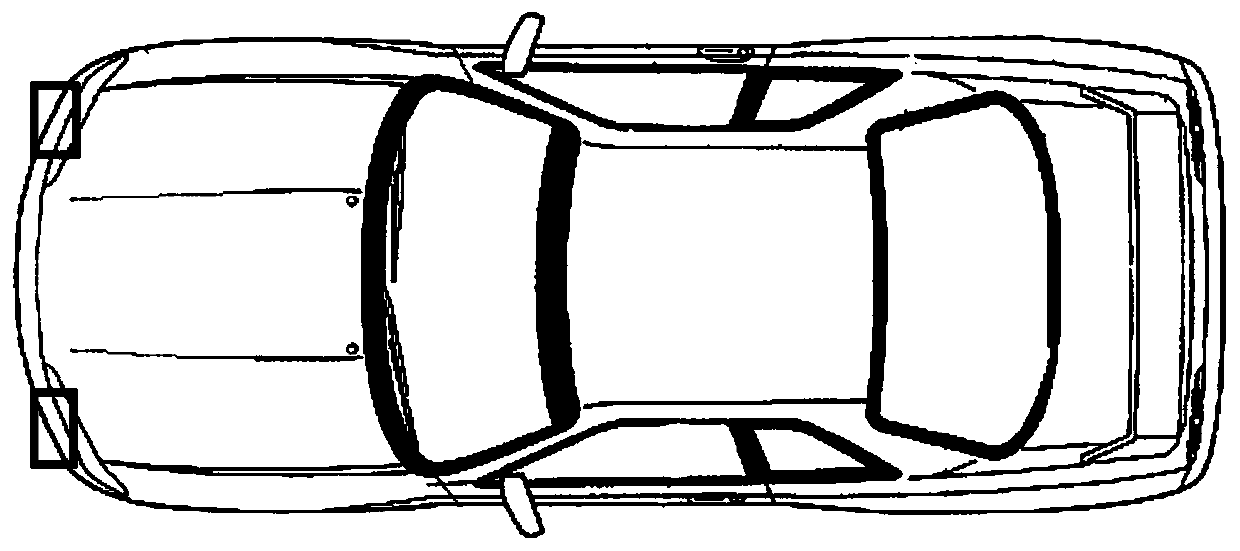
[0053] refer to Figure 5 , is the second embodiment of the present invention. This embodiment is different from the first embodiment in that it provides a driving anti-slip pre-control system based on road surface recognition, which includes an identification module 100, a calculation module 200 and a control module. 300. The identification module 100 uses two cameras installed at the front bumper of the vehicle to identify the road surface that the left and right wheels are about to drive through, and through the identification of the state of the road surface, respectively determine the slip rate limit of the high and low adhesion coefficient road surface, Control the road surface adhesion utilization ratio of each wheel to the vicinity of the maximum value; the calculation module 200 calculates the minimum adhesion force that the road surface can provide by combining the vertical load of each wheel, calculates the relevant data formula, and obtains the maximum value of the...


PUM


Abstract

The invention discloses an acceleration slip regulation control method and system based on road surface recognition. The control method comprises the following steps of detecting and recognizing a road surface by utilizing cameras on a vehicle; calculating the road surface to be driven by four wheels; calculating the load of each wheel by using force sensors; calculating the maximum adhesion forceof each wheel corresponding to the road surface by using a road surface adhesion coefficient definition formula and an adhesion coefficient table; obtaining the maximum value of the driving force ofeach wheel; and controlling the driving force of four motors to be always smaller than or equal to F<max>. The acceleration slip regulation control method and system based on the road surface recognition solve the problem that the control is applied when the wheels slip, and a pre-control system is additionally arranged; and the road surface to be driven is detected and recognized through the cameras, the driving force of the motors is correspondingly reduced in advance if the road surface adhesion coefficient becomes smaller, and the wheels do not slip when the output torque of the motors issmaller than the minimum adhesion force provided by the road surface.

Description

technical field [0001] The invention relates to the technical field of four-wheel independent drive anti-skid and road surface recognition, in particular to a method and system for pre-controlling anti-skid drive based on road surface recognition. Background technique [0002] Vehicle drive anti-skid technology has a long history. As early as the 1970s, automotive engineers began to pay attention to the problem of excessive slippage of driving wheels and carried out a series of related research. In 1971, Buick developed the electronic control device to automatically interrupt the engine ignition to reduce the engine output torque and prevent the drive wheel from slipping; Produced by automobile companies, in order to achieve the maximum utilization of the road surface adhesion coefficient and obtain the largest possible traction force, the first mass-produced ASR selects the driving slip rate as the control parameter, and sets the lower threshold of its control at 5%. The l...

Claims


Application Information

Patent Timeline
IPC IPC(8): B60W30/18B60W40/06B60W50/00B60L15/38
CPCB60W30/18109B60W40/06B60W50/00B60L15/38B60W2710/083B60W2050/0019B60W2050/0037B60W2420/42
Inventor 薛斌
Owner 的卢技术有限公司
Why Eureka
Try Eureka