Cloth feeding mechanism of digital printing machine

A technology of a digital printing machine and a guiding mechanism, applied in the field of digital printing machines, can solve problems such as difficulty in controlling force balance, inconvenient adjustment of counterweights, inability to eliminate loose sticking, etc., to achieve compact structure, improve printing quality and structure. scientific compact effect

Active Publication Date: 2020-02-28
广东希望高科数字技术有限公司
View PDF6 Cites 10 Cited by
  • Summary
  • Abstract
  • Description
  • Claims
  • Application Information

AI Technical Summary

Problems solved by technology

[0003] However, the cloth loading mechanism of the existing digital printing machine has the following disadvantages: (1) it needs to be equipped with a separate cloth rack; (2), the edge alignment device only aligns the edge during the cloth running process, which requires a lot of space to carry out Cushioning; (3) The position of the moving roller is fixed, and there is no chance to eliminate the creases of the cloth during printing; (4) The moving roller has no heating device, so that the cloth can be more closely attached to the printing conveyor belt; it is impossible to eliminate the wrinkles caused by

Method used


Image

  • Cloth feeding mechanism of digital printing machine
  • Cloth feeding mechanism of digital printing machine
  • Cloth feeding mechanism of digital printing machine

Examples


Embodiment Construction

[0036] The present invention and its beneficial technical effects will be further described in detail below in conjunction with the accompanying drawings and preferred embodiments.

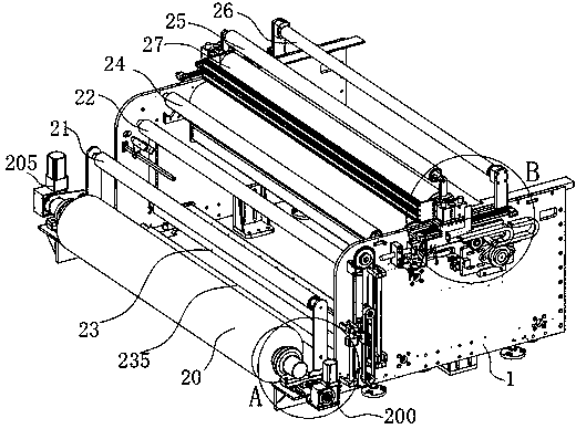
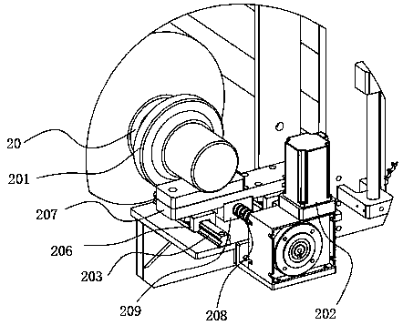
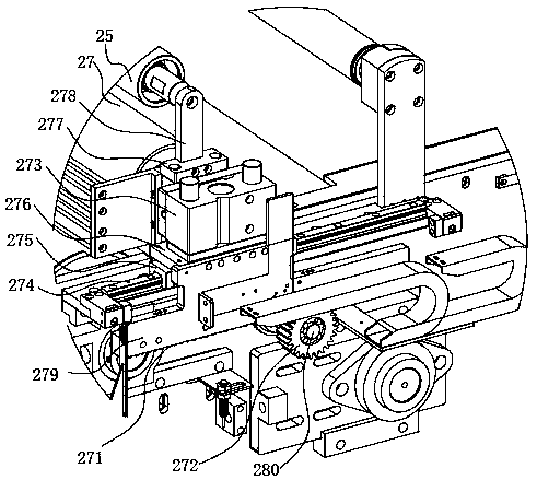
[0037] see Figure 1~Figure 13 The cloth loading mechanism of the digital printing machine preferably implemented in the present invention includes a frame 1, and an air expansion shaft 20 arranged on the frame 1, a large wrap angle roller 21, a cloth passing roller a22, a constant tension floating roller 23, a passing Cloth roller b24, cloth passing roller c25, moving roller 27, widening angle wrapping roller 26; the rear side of frame 1 is the cloth feeding side; it is characterized in that, the air expansion shaft 20, large roll wrapping angle roller 21, passing The cloth roller a22, the cloth passing roller b24, and the cloth passing roller c25 are arranged at intervals along the forward direction of the cloth; the constant tension floating roller 23 can be lowered between the cloth passing ro...


PUM


Abstract

The invention discloses a cloth feeding mechanism of a digital printing machine. The cloth feeding mechanism of the digital printing machine comprises a machine frame, an air expansion shaft, a largeroll corner wrapping roller, a cloth passing roller a, a constant-tension floating roller, a cloth passing roller b, a cloth passing roller c, a moving roller and a width increase corner wrapping roller. The air expansion shaft, the large roll corner wrapping roller, the cloth passing roller a, the constant-tension floating roller, the cloth passing roller b, the cloth passing roller c, the movingroller and the width increase corner wrapping roller are arranged on the machine frame. An unwinding driving device is arranged at one end of the air expansion shaft. Lifting guide mechanisms and a floating lifting driving device are arranged on the machine frame and drive the constant-tension floating roller to move. A horizontal movement driving device for front-and-rear sliding mechanisms which allow the moving roller to horizontally move is arranged on the machine frame. An unwinding deviation correcting system which conducts position correction on a piece of cloth is arranged on the machine frame. The cloth feeding mechanism of the digital printing machine has the advantages that the cloth feeding mechanism is matched with large rolls of cloth and small rolls of cloth, a cloth framedoes not need to be independently arranged, and the cost is saved; the cloth feeding mechanism has the function that the deviation correction and the edge alignment are automatically conducted on thecloth in real time; the cloth can be closely attached to a conveying belt, few press marks exist, no fold exists, a spray nozzle is protected, and the printing quality is improved; a single air cylinder is adopted so that the control over the value of the constant tension of the constant-tension floating roller can be achieved; and the jam phenomenon is avoided.

Description

technical field [0001] The invention relates to a digital printing machine, in particular to a cloth loading mechanism of the digital printing machine. Background technique [0002] Digital printing machines are widely used in clothing, cutting pieces, clothing, leather, luggage, transfer paper, artificial flowers, shoe materials, flocking cloth, thick plate, cloth, etc. At present, the cloth loading mechanism of the digital printing machine includes the frame, the cloth loading frame, and the large wrapping angle roller, the cloth passing roller, the constant tension roller, the pressure roller, and the expanding angle wrapping roller arranged on the frame; There is a device for aligning the fabric; the constant tension roller is equipped with a constant tension mechanism to maintain tension, and the constant tension mechanism adopts counterweights or cylinders are installed at both ends of the constant tension roller. When in use, it needs to be equipped with a cloth rack...

Claims


Application Information

Patent Timeline
IPC IPC(8): B65H23/26B65H23/038
CPCB65H23/038B65H23/26
Inventor 何小燕
Owner 广东希望高科数字技术有限公司
Why Eureka
Try Eureka