
Mechanism for switching light emitting diode (LED) light sources by using electromagnetic valve

A technology of LED light source and solenoid valve, applied in the field of automotive lighting, can solve the problems such as the inability to use LEDs with maximum efficiency, increase the power or quantity of LEDs, and the inability to share LEDs, etc., to achieve easy displacement, improve LED light efficiency, and ensure accuracy. Effect

Pending Publication Date: 2020-02-28
MAGNETI MARELLI AUTOMOTIVE COMPONENTS WUHU
View PDF0 Cites 1 Cited by
  • Summary
  • Abstract
  • Description
  • Claims
  • Application Information

AI Technical Summary

Problems solved by technology

The LED light sources of the daytime running light and the turn signal are gathered under the head of the light guide, but since the LED light emission color of the daytime running light is white or amber, and the light color of the turn signal LED is yellow, the two functions cannot share the LED, but use different leds
In order to balance the LED light effect of the daytime running lights and turn signals in the existing design, the optical centers of the two LEDs are not directly facing the center of the light guide head, and the light emitted by the LEDs cannot be utilized to the maximum efficiency.
In order to meet the requirements of the regulations on the brightness of daytime running lights and turn signals, the existing design has to increase the power or number of LEDs
This requires the lamp to have better heat dissipation capability and also increases the cost

Method used


Image

  • Mechanism for switching light emitting diode (LED) light sources by using electromagnetic valve
  • Mechanism for switching light emitting diode (LED) light sources by using electromagnetic valve
  • Mechanism for switching light emitting diode (LED) light sources by using electromagnetic valve

Examples


Embodiment Construction

[0020] In order to deepen the understanding of the present invention, the present invention will be further described below in conjunction with the examples, which are only used to explain the present invention, and do not constitute a limitation to the protection scope of the present invention.

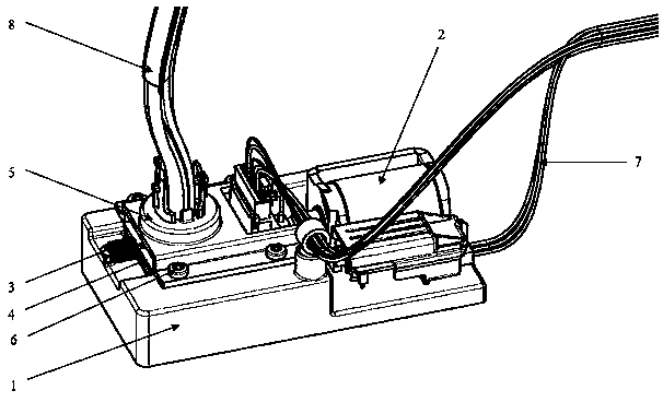
[0021] Such as figure 1 As shown, this embodiment provides a mechanism for switching LED light sources using a solenoid valve, including a bracket 1 , a solenoid valve 2 , a spring 3 , a PCBA assembly 4 , a light guide adapter bracket 5 , a screw 6 , a wire harness 7 and a light guide 8 .

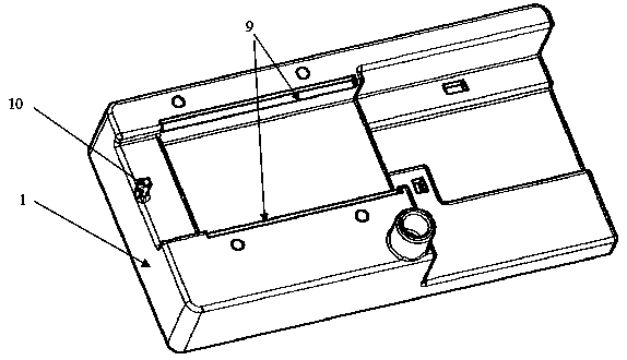
[0022] Such as figure 2 As shown, there is a guide track 9 on the support 1 . The guide rail 9 is a linear guide rail, which makes it easier to control the displacement of the PCBA assembly; the circumference of the guide rail is modeled after the shape of the PCBA assembly 4, which can effectively reduce the position tolerance of the PCBA assembly and ensure accuracy. Wherein the guide rail 9 ...


PUM


Abstract

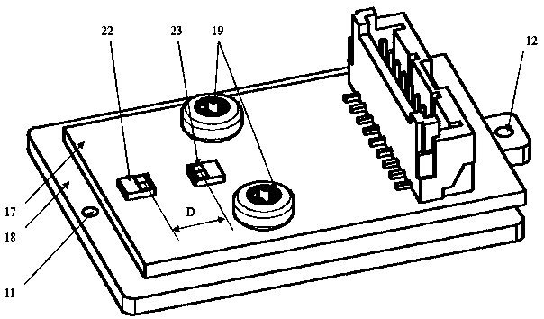
The invention provides a mechanism for switching light emitting diode (LED) light sources by using an electromagnetic valve. The two light sources are arranged on a printed circuit board assembly (PCBA), and when the electromagnetic valve is not electrified, the second light source works, and the second light source is located directly below the center of the end face of the head of a light guideat the moment. When the electromagnetic valve is electrified, the head of the electromagnetic valve can pull the PCBA to move to the right for a certain distance, and can enable the first light sourceto move to the position directly below the center of the end face of the head of the light guide, and at the moment, the second light source does not work, and the first light source starts to work.The mechanism for switching the LED light sources by using the electromagnetic valve realizes switching of the first light source and the second light source under the action of the electromagnetic valve, enables the light sources to always locate directly below the center of the end face of the head of the light guide in working, and effectively improves LED lighting effects.

Description

technical field [0001] The invention relates to the field of automobile lighting, in particular to a mechanism for switching LED light sources using a solenoid valve. Background technique [0002] With the rapid development of the automobile industry, the competition in the automobile industry is becoming more and more fierce. Various automobile groups are constantly introducing new ones, and they are constantly putting forward new requirements and new ideas for auto parts, especially for the appearance of automobile headlights. And the energy-saving performance is even more refined, which also makes the application of LEDs in automotive lamps more and more extensive. For example, LEDs are used as light sources combined with light guides to realize the functions of daytime running lights and turn signals. [0003] Using LED as light source combined with light guide to realize the two functions of daytime running light and turn signal is a very common design in the market now...

Claims


Application Information

Patent Timeline
Patent Type & Authority Applications(China)
IPC IPC(8): F21V23/04F21V21/35F21Y115/10
CPCF21V23/04F21V21/35F21Y2115/10F21S43/237F21S43/27F21S43/14F21S43/195F21W2103/20F21W2103/55B60Q1/2607B60Q2400/20
Inventor 孙子旺
Owner MAGNETI MARELLI AUTOMOTIVE COMPONENTS WUHU
Learn More