
Method for producing a bipolar plate strand, method for producing a bipolar plate and device for carrying out the method

a technology of bipolar plates and strands, applied in the direction of electrochemical generators, sustainable manufacturing/processing, final product manufacturing, etc., can solve the problems of local leakage in terms of media flow, leakage statistically, and pore formation

Pending Publication Date: 2022-05-12
AUDI AG
View PDF0 Cites 1 Cited by
  • Summary
  • Abstract
  • Description
  • Claims
  • Application Information

AI Technical Summary

Benefits of technology

The patent text describes a method for producing a bipolar plate strand, which can be used in a fuel cell stack. The method involves heating and relaxing the bipolar plate strand using a heating device, which increases the strength of the connection between the two unipolar plates. The bipolar plate strand can then be divided into individual bipolar plates using a cutting device, which reduces position tolerances and improves welding quality. This method also reduces the risk of leaks and production scrap. The device uses a laser device with good control over the heat source, allowing for robust process management and high welding quality.

Problems solved by technology

It has been found that with such laser-welded bipolar plates there is a risk of pore formation, which can lead to local leaks in terms of media flow.
Such leaks occur statistically in particular on welds that extend particularly far.
It is also known that leaks occur more frequently at the start and end of the seam, i.e., the risk of leaks increases with the number of weld seams used and their length.
In addition, it has proven to be complex and difficult for laser welding to be able to clamp the two unipolar plates in a clamping device in such a way that the laser beam hits the desired point to be welded in a focused manner.

Method used

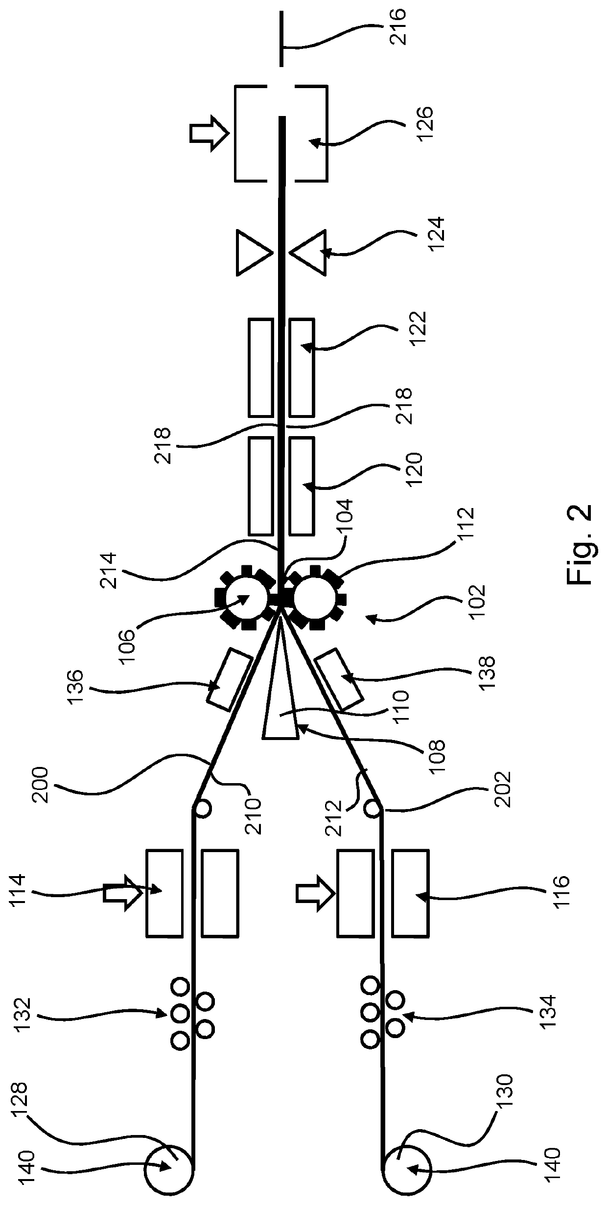
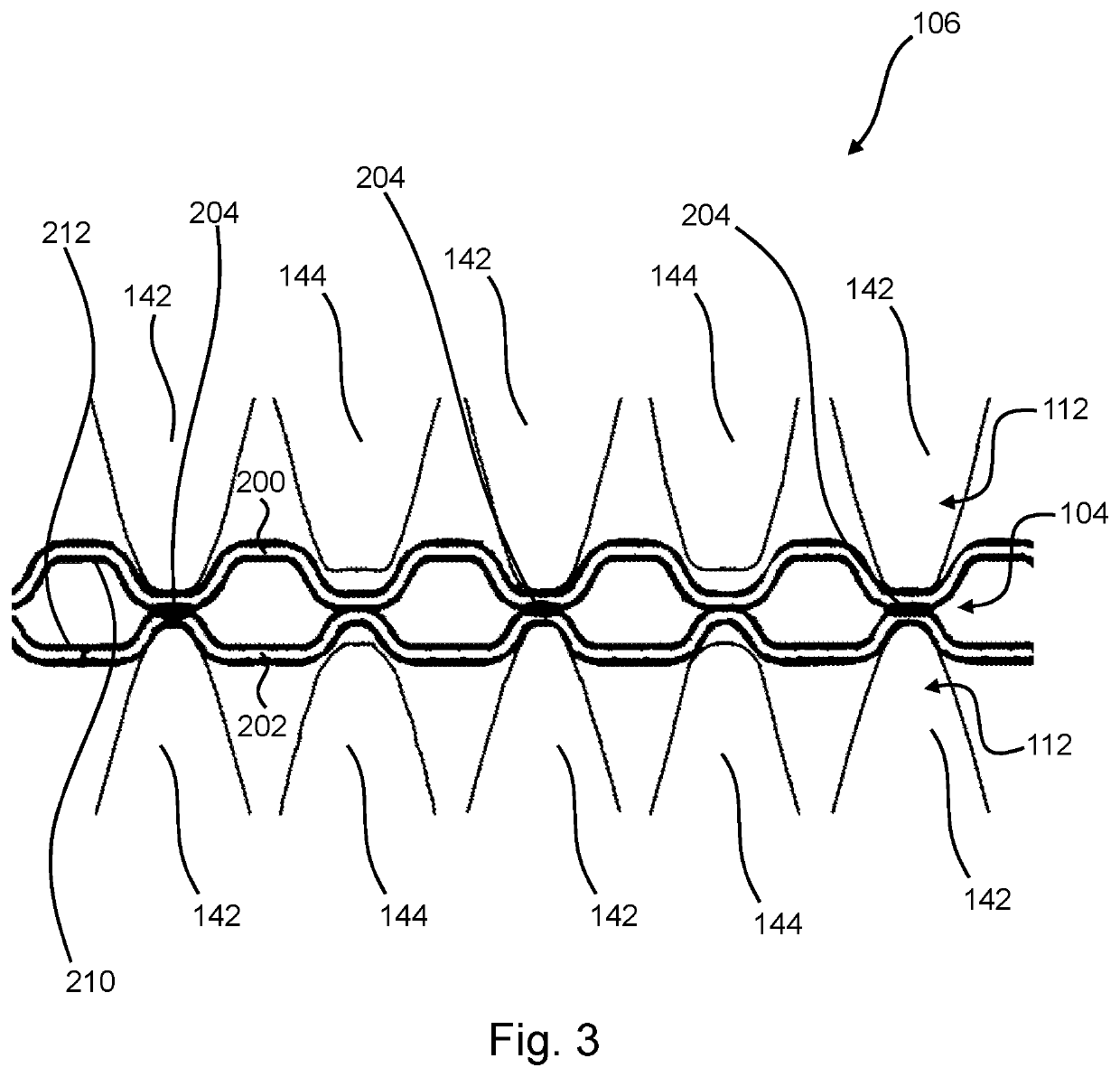

Image

  • Method for producing a bipolar plate strand, method for producing a bipolar plate and device for carrying out the method
  • Method for producing a bipolar plate strand, method for producing a bipolar plate and device for carrying out the method
  • Method for producing a bipolar plate strand, method for producing a bipolar plate and device for carrying out the method

Examples


Embodiment Construction

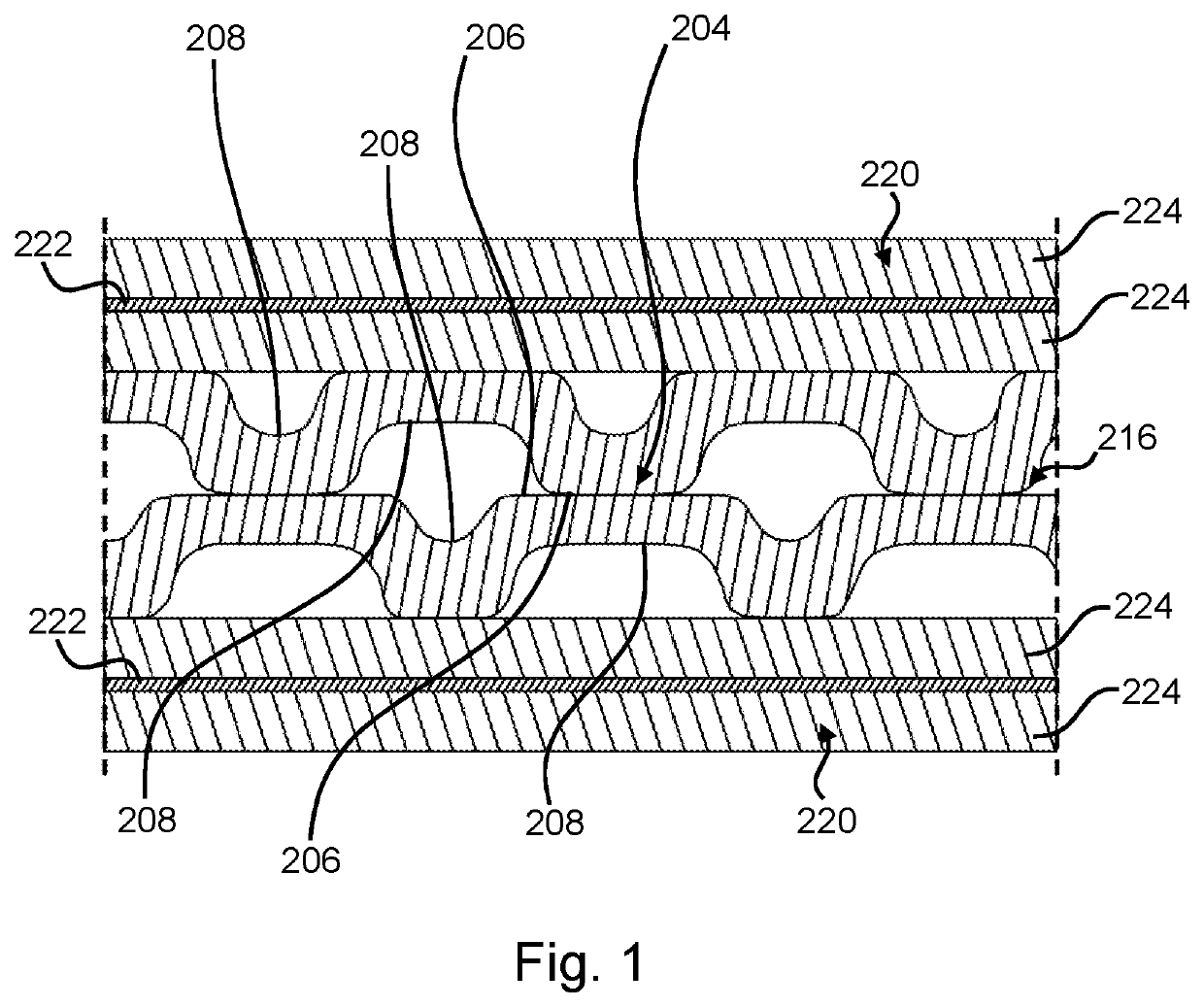
[0052]In FIG. 1, the section of a fuel cell stack can be seen, which is formed from several fuel cells 220. Each fuel cell 220 is formed with a membrane electrode assembly 222, which comprises a proton conductive membrane, to which an electrode is assigned on each side. Membrane electrode assembly 222 is configured to carry out the electrochemical reaction of the fuel cell. For this purpose, fuel (e.g., hydrogen) is fed to the electrode forming the anode, where it is catalytically oxidized to form protons by releasing electrons. These protons are transported to the cathode through the proton-conductive membrane (or ion exchange membrane). The electrons dissipated from the fuel cell flow via an electrical load, such as via an electric motor, to the drive system of a vehicle, or to a battery. Then, the electrons are conducted to the cathode or electrons are provided at the cathode. At the cathode, the oxidation medium (e.g., oxygen or air containing oxygen) is reduced to anions by tak...


PUM

PropertyMeasurementUnit
Temperatureaaaaaaaaaa
Pressureaaaaaaaaaa
Surface areaaaaaaaaaaa

Abstract

A method for producing a bipolar plate strand comprises: providing a first and a second unipolar plate strand, the unipolar plate strands comprising a plurality of webs and a plurality of channels extending between two adjacent webs in each case, guiding the unipolar plate strands towards a rolling gap of a pair of rollers of a rolling device provided with rolling structures, local heating of one surface area of a surface of at least one of the unipolar plate strands, the surface area immediately before or upon entry of the unipolar plate strands into the rolling gap being heated to a joining temperature, and joining the unipolar plate strands at the at least one surface area to form a bipolar plate strand during transport of the unipolar plate strands through the rolling gap under the action of pressure.

Description

BACKGROUNDTechnical Field[0001]Embodiments of the invention relate to a method for producing a bipolar plate strand which has a plurality of contiguous bipolar plates of a fuel cell. Embodiments of the invention also relate to a method for producing a bipolar plate of a fuel cell, and a device for carrying out the two methods.Description of the Related Art[0002]Bipolar plates are used in fuel cells and fuel cell stacks. Using the bipolar plates, on the one hand, the fuel is conveyed and distributed to an adjacent anode of a first fuel cell and the cathode gas is conveyed and distributed to a cathode of an adjacent second fuel cell, the bipolar plate also providing lines for conveying a cooling medium. A bipolar plate is usually made from two unipolar plates formed as half-shells, which are glued together in the case of bipolar plates made of graphite. Metallic bipolar plates typically comprise two unipolar plates welded to one another at least in sections.[0003]US 2005 / 0252 892 A1 d...

Claims


Application Information

Patent Timeline
IPC IPC(8): H01M8/0297B23K20/00H01M8/0267H01M8/0206
CPCH01M8/0297H01M8/0206H01M8/0267B23K20/008H01M8/0254B23K2101/14Y02E60/50Y02P70/50
Inventor BLOEHS, WOLFGANG
Owner AUDI AG
Learn More