

Method for monitoring compression and tensile deformation of stressed rod piece based on optical fiber sensing technology
An optical fiber sensing and tensile deformation technology, which is used in measuring devices, using stable tension/pressure to test the strength of materials, instruments, etc., can solve the problem of inability to obtain data quickly, low monitoring coverage density, and inability to ensure the personal safety of measurement personnel. and other problems, to achieve the effect of non-interference measurement, sensitivity and accuracy improvement, and high sensitivity
- Summary
- Abstract
- Description
- Claims
- Application Information
AI Technical Summary
Problems solved by technology
Method used
Image

Examples
Embodiment
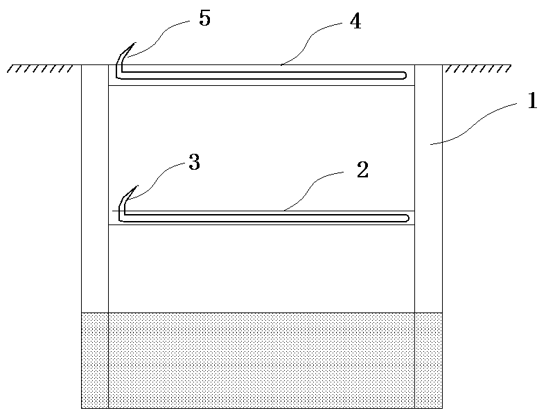
[0027] Example: such as Figure 1-4 As shown, this embodiment specifically relates to a method for monitoring the compression and tensile deformation of a stressed rod based on optical fiber sensing technology, which specifically includes the following steps:
[0028] (1) According to the engineering needs, determine the area of the supporting rods to be tested in the foundation pit enclosure structure 1, and determine the distance between each fixing ring according to the needs;
[0029] (2) For different types of support rods, choose different installation methods:
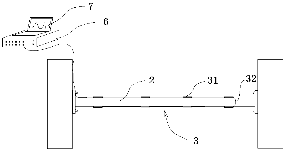
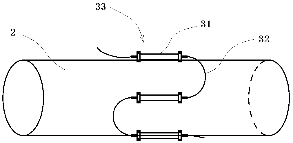
[0030] If the support bar is a concrete support 4, then the quasi-distributed steel stress sensing optical cable 5 is arranged along the axial direction of the concrete support 4, and the quasi-distributed steel stress sensing optical cable 5 is specifically bundled and arranged in two symmetrically arranged in the concrete support 4. on the main bar, and form a U-shaped return circuit; the quasi-distributed ...
PUM
 Abstract
Description
Claims
Application Information