Display panel, device and method, electrowetting microcavity unit and light control substrate

A display panel and display device technology, which is applied in optics, optical components, nonlinear optics, etc., can solve problems such as non-adjustability, and achieve the effect of high light utilization rate and high display brightness

Pending Publication Date: 2020-02-28
BOE TECH GRP CO LTD
View PDF7 Cites 1 Cited by
  • Summary
  • Abstract
  • Description
  • Claims
  • Application Information

AI Technical Summary

Problems solved by technology

Limited by the material of the lenticular lens itself, parameters such as focal length and grating distance are fixed and cannot be adjusted

Method used


Image

  • Display panel, device and method, electrowetting microcavity unit and light control substrate
  • Display panel, device and method, electrowetting microcavity unit and light control substrate
  • Display panel, device and method, electrowetting microcavity unit and light control substrate

Examples


Embodiment Construction

[0051] The present application is described in detail below, and examples of embodiments of the present application are shown in the drawings, wherein the same or similar reference numerals denote the same or similar components or components having the same or similar functions throughout. Also, detailed descriptions of known technologies will be omitted if they are not necessary to illustrate the features of the present application. The embodiments described below by referring to the figures are exemplary only for explaining the present application, and are not construed as limiting the present application.

[0052] Those skilled in the art can understand that, unless otherwise defined, all terms (including technical terms and scientific terms) used herein have the same meanings as commonly understood by those of ordinary skill in the art to which this application belongs. It should also be understood that terms, such as those defined in commonly used dictionaries, should be ...


PUM


Abstract

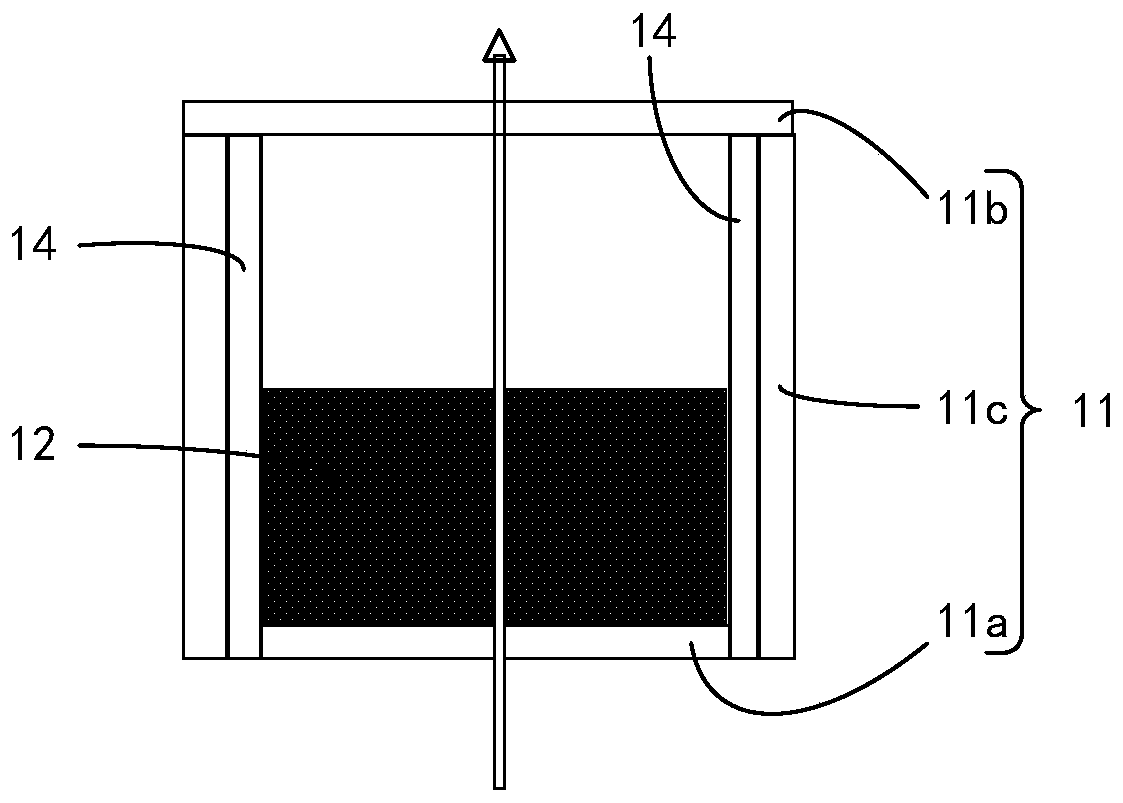
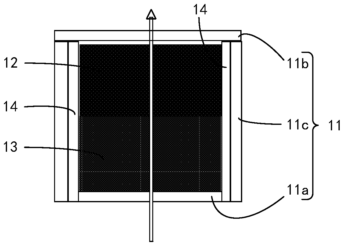
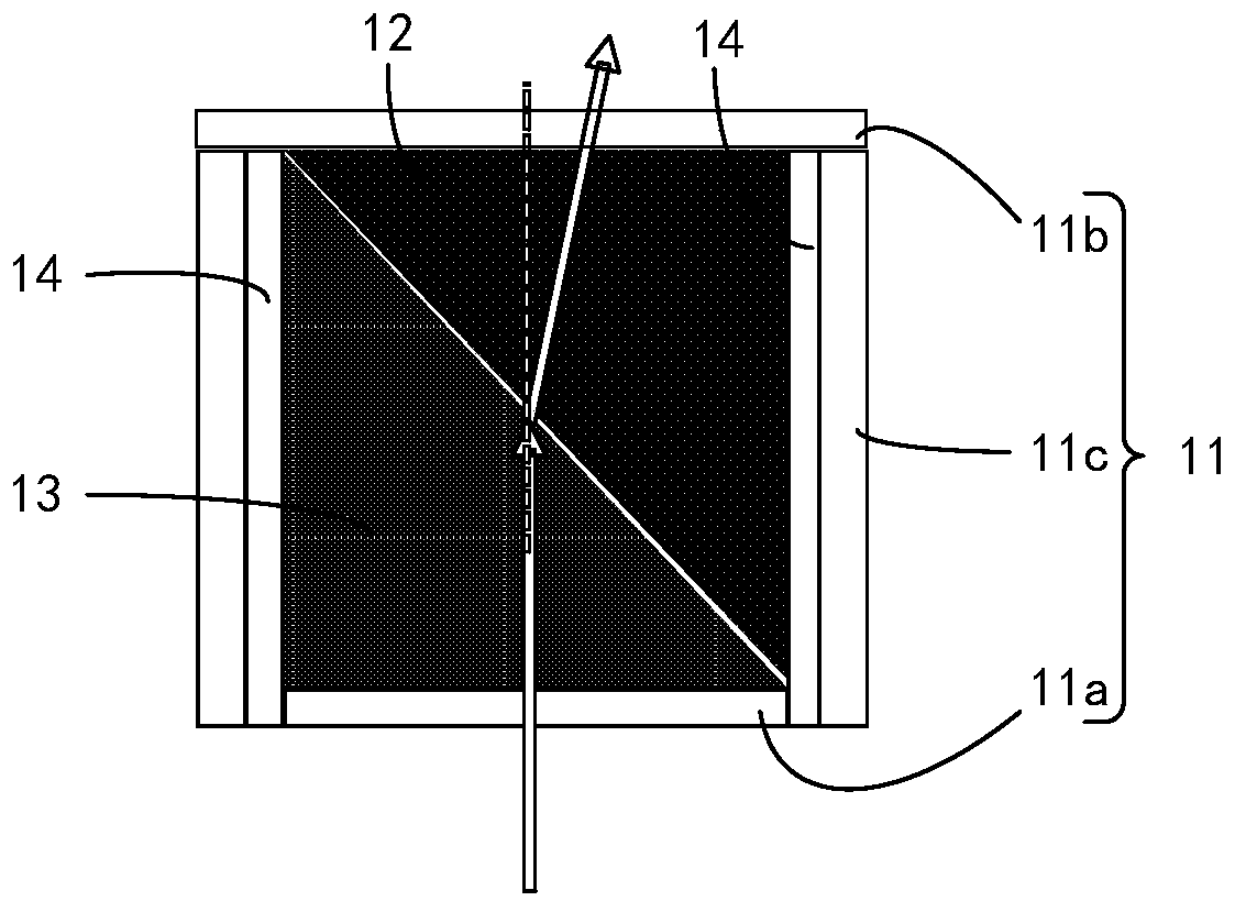
The embodiment of the invention provides a display panel, device and method, an electrowetting microcavity unit and a light control substrate. The electrowetting microcavity unit comprises an electrowetting cavity and electrowetting liquid, wherein the electrowetting cavity is provided with a peripheral surface, a first light-transmitting bottom surface and a second light-transmitting bottom surface; the first light-transmitting bottom surface and the second light-transmitting bottom surface are used for packaging the two ends of the peripheral surface respectively; a partial space in the electrowetting cavity is filled with the electrowetting liquid; any two adjacent surfaces of the peripheral surface, the first light-transmitting bottom surface and the second light-transmitting bottom surface are insulated, at least two surfaces are provided with electrodes, and the electrode of at least one surface is a grounding electrode. According to the embodiment of the invention, light passesthrough the electrowetting liquid, and the angle of the incident surface and / or the emergent surface of the electrowetting liquid can be adjusted by controlling the electric field, so that the light is projected to different directions, binocular parallax is formed, and three-dimensional image display is realized; and moreover, light is not shielded, and the light utilization rate is high.

Description

technical field [0001] The present application relates to the field of display technology, in particular, the present application relates to a display panel, a device and a method, an electrowetting microcavity unit, and a light control substrate. Background technique [0002] Glasses-free 3D (three-dimensional) display utilizes the parallax characteristic of human eyes to obtain realistic three-dimensional images with space and depth without any auxiliary equipment (such as 3D glasses, helmets, etc.). [0003] Existing glasses-free 3D displays usually adopt light barrier technology or lenticular lens technology. [0004] Light barrier technology uses a barrier to separate light into left-eye and right-eye direction light to form binocular parallax to achieve stereoscopic image display, but it inevitably blocks part of the light, resulting in low light utilization, that is, the display brightness is low. Low. [0005] Lenticular lens technology is to make the image plane o...

Claims


Application Information

Patent Timeline
IPC IPC(8): G02B26/00G02B30/28G02F1/1335G09G3/34
CPCG02B26/005G02F1/133526G09G3/348
Inventor 孟宪芹孟宪东王维陈小川田依杉王方舟凌秋雨刘佩琳
Owner BOE TECH GRP CO LTD
Why Eureka
Try Eureka