
Battery cell charging method, battery full-life-cycle charging method and system

A technology of full life cycle and charging method, which is applied in the battery full life cycle charging method and system, and the field of battery charging, which can solve problems such as weak dependence on historical data, increased cost, and impossibility of batteries

Active Publication Date: 2020-02-28
CHANGXING TAIHU ELECTRIC CORP
View PDF5 Cites 2 Cited by
  • Summary
  • Abstract
  • Description
  • Claims
  • Application Information

AI Technical Summary

Problems solved by technology

Due to the consideration of power consumption and cost, the balance current of the traditional active battery management system is generally around 5A. Therefore, its balance ability is limited, and the requirements for battery cells in groups are high.
In addition, the balance method of the active battery management system is not closely related to the charging algorithm; and the active balance algorithm is controlled by the model and has a weak dependence on historical data
[0006] It can be seen that during the charging process, the weak cell balancing ability of the existing battery management system has greatly increased the battery system's requirements for cell consistency, which will greatly increase the cost on the one hand, and on the other hand, as the charging speed increases , the charging current becomes larger, and the balance between the cells becomes impossible, which leads to overcharging of some cells and accelerates the aging of the battery
Seriously, it will also cause thermal runaway of the battery and cause a safety accident

Method used


Image

  • Battery cell charging method, battery full-life-cycle charging method and system
  • Battery cell charging method, battery full-life-cycle charging method and system
  • Battery cell charging method, battery full-life-cycle charging method and system

Examples


Embodiment Construction

[0084] The following are specific embodiments of the present invention and in conjunction with the accompanying drawings, the technical solutions of the present invention are further described, but the present invention is not limited to these embodiments.

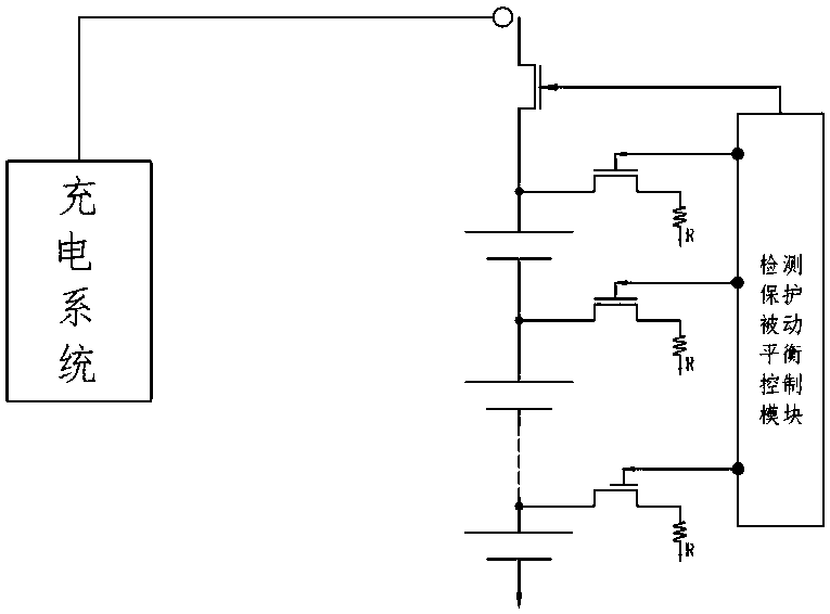
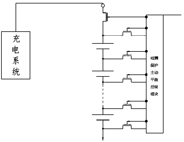
[0085] Existing battery management systems, whether active (such as figure 2 ) or passive (such as figure 1) battery management system, all use intervention methods to prevent overcharging of batteries. However, during the intervention process, although the passive battery management system consumes the overcharge capacity of a single cell through an external resistive load, overheating under long-term use of the resistive load tends to generate more power consumption. Although the active battery management system can coordinate the energy conversion between the cells through the switch matrix to prevent the cells from being overcharged, it also has the problems of high power consumption and limited and small balancing a...


PUM


Abstract

The invention discloses a battery cell charging method and a battery full-life-cycle charging method and system, and belongs to the battery management field. The battery cell charging method comprisesthe following steps of if a charging current is controlled within a safe range and second charging time tc2 is not less than first charging time tc1, carrying out tc1 charging on a battery cell; andif a charging voltage is controlled within the safe range and the tc1 is not less than the tc2, carrying out tc2 charging on the battery cell, wherein the tc1 is longest time when the battery cell isunder an overcharge voltage during charging and an irreversible damage is not formed yet; the tc2 is the longest time when the battery cell is under an overcharge current during charging, and the irreversible damage is not formed yet. The battery charging method comprises the following steps of calculating a charging pulse of a next moment according to real-time data of the battery, the tc1, the tc2 and change information of first relaxation time and second relaxation time so that the battery has the longest time of the highest bearable charging voltage or the highest charging current in a healthy state till that the battery is fully charged. In the invention, under a condition that a requirement of consistency of the battery cell is reduced, low-cost and good-balance rapid charging is realized.

Description

technical field [0001] The invention relates to the technical field of battery management, in particular to a battery charging method, a battery full life cycle charging method and a system. Background technique [0002] Electrochemical energy storage has many advantages, such as short construction period and return on investment period, low environmental requirements, distributed construction, and suitable for distributed renewable energy storage. Therefore, it is one of the important energy storage technologies for the Energy Internet. How to develop a battery system with high safety, good economy, environmental protection and good reproducibility is the core problem of solving distributed energy storage. [0003] Charging technology is one of the keys to the healthy and safe use of battery systems. Unreasonable charging methods will greatly shorten battery life, and even cause potential safety hazards. The recent frequent spontaneous combustion of lithium battery electr...

Claims


Application Information

Patent Timeline
IPC IPC(8): H02J7/00G01R31/382G01R31/396
CPCH01M10/44H02J7/0013H02J7/0014H02J7/007H01M10/425H01M10/441H01M10/48H02J7/0016H02J7/0048H02J7/005H02J7/00711H02J7/007194Y02E60/10G01R31/3648G01R31/374G01R31/3842G01R31/396H02J7/0063H02J7/00304H02J7/00308H02J7/0071H02J7/00712H02J7/00714H02J7/007182H02J7/007192
Inventor 吴建斌
Owner CHANGXING TAIHU ELECTRIC CORP
Learn More