Efficient ejector

An ejector and high-efficiency technology, which can be used in ejection devices, liquid ejection devices, etc., can solve the problems of generating eddy currents, shock waves, eddy currents, etc., and achieve the effects of smooth velocity gradient changes, reduced energy loss, and smooth velocity changes.

Pending Publication Date: 2020-03-06
NINGBO INST OF TECH ZHEJIANG UNIV ZHEJIANG
View PDF1 Cites 3 Cited by
  • Summary
  • Abstract
  • Description
  • Claims
  • Application Information

AI Technical Summary

Problems solved by technology

[0005] Although the injector with the above-mentioned structure improves the system efficiency to a certain extent, its performance is closely related to its own structure. The main loss is that the speed of the working fluid and the injection fluid are different before mixing, resulting in vortex phenomenon, and the mixing process. Shock wave phenomenon after mixing
According to the Bernoulli equation, the working fluid exp

Method used


Image

  • Efficient ejector
  • Efficient ejector
  • Efficient ejector

Examples


Example Embodiment

[0031] Example

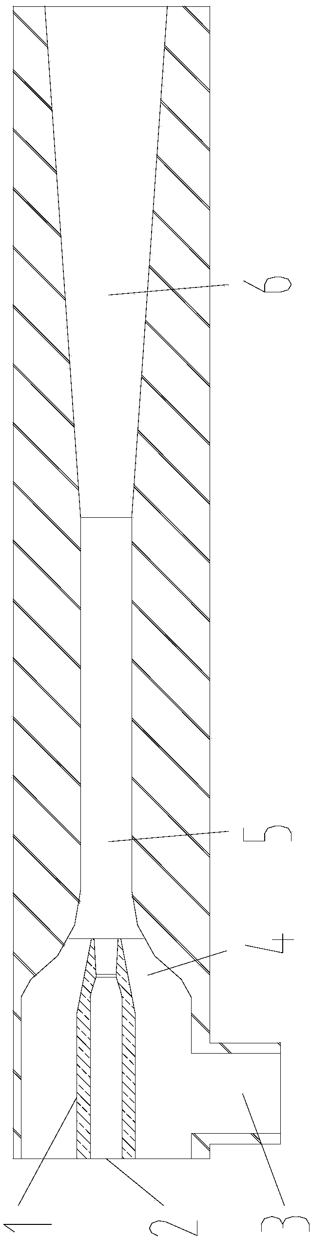
[0032] Such as figure 1 As shown, the high-efficiency ejector of this embodiment includes: a working nozzle 1, a working fluid inlet 2, a jet fluid inlet 3, a receiving chamber 4, a mixing chamber 5 and a diffusion chamber 6.

[0033] The working nozzle 1 communicates with the working fluid inlet 2, the ejection fluid inlet 3 communicates with the receiving chamber 4, the working nozzle 1 and the receiving chamber 4 communicate with the mixing chamber 5, and the mixing chamber 5 communicates with the diffusion chamber 6 respectively.

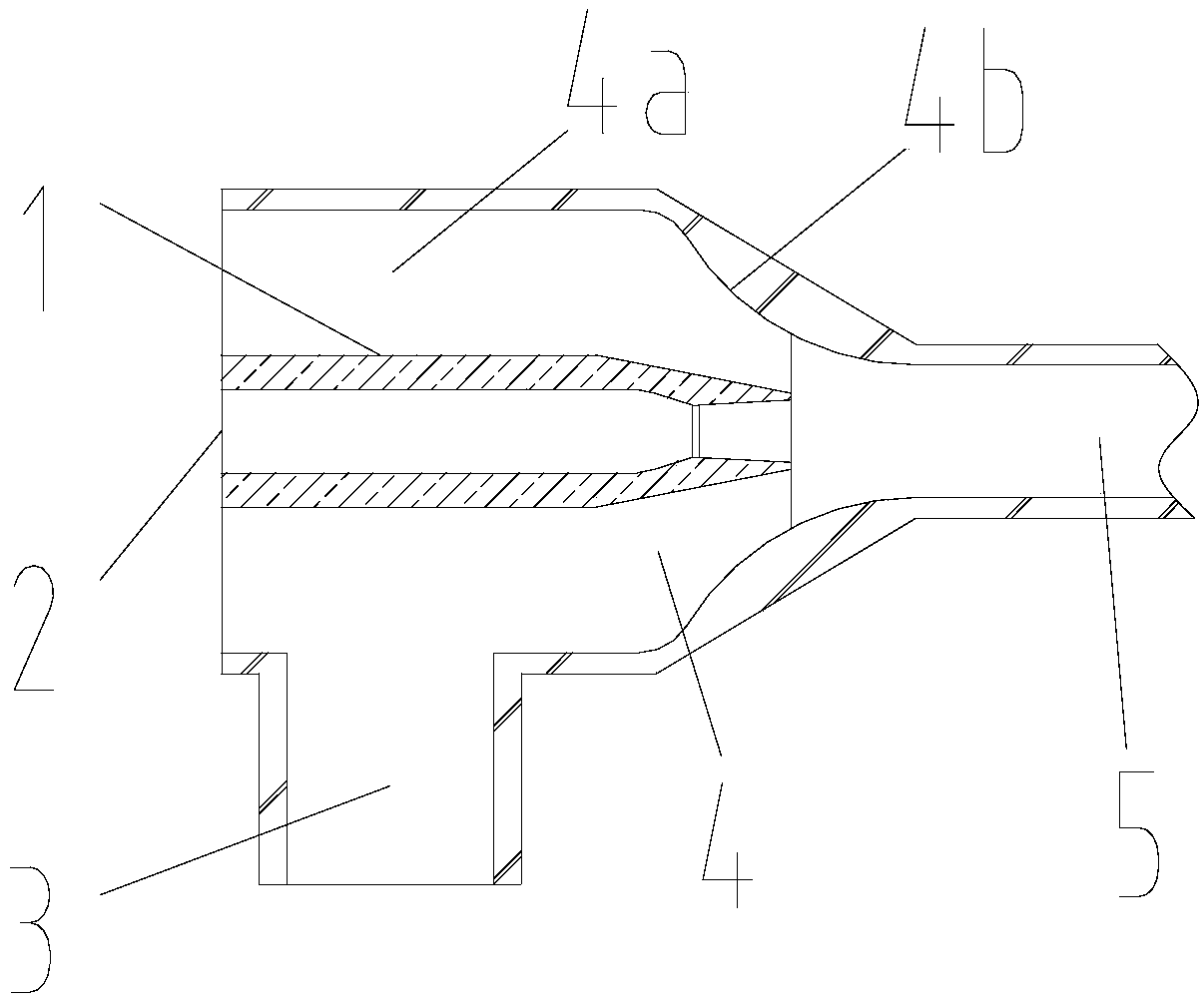
[0034] Such as figure 2 As shown, the receiving chamber 4 includes the body cavity 4a and the receiving chamber contraction section 4b connected with the body cavity 4a. The curve of the receiving chamber 4b is designed according to the Vitosinski curve to reduce the speed of the working fluid and the ejector fluid when mixing. Energy loss caused by difference.

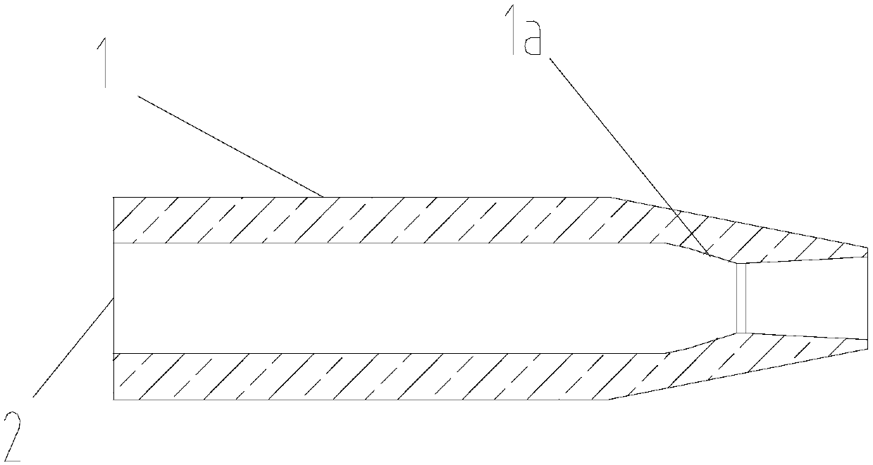
[0035] Such as image 3 As shown, the working nozzle 1 adopts a zoom stru...


PUM


Abstract

The invention discloses an efficient ejector. The ejector comprises a working nozzle, a receiving chamber, a mixing chamber and a diffusion chamber, wherein the working nozzle, the receiving chamber,the mixing chamber and the diffusion chamber communicate with one another; the working nozzle comprises a tapered section and a diverging section, wherein the tapered section is located at the upstream of a throat according to the flow direction with the flow cross-sectional area gradually reduced in the direction of fluid flow, and is connected with a working fluid inlet; the diverging section islocated at the downstream of the throat according to the flow direction with the flow cross-sectional area gradually increased in the direction of fluid flow; and the tapered section comprises a front section and a rear section, wherein the change of the flow cross-sectional area of the rear section is more gradual than that of the front section. According to the efficient ejector, the tapered section of the working nozzle adopts a Vitosinsky type line, so that the speed change of working fluid and injection fluid is more gradual, the energy loss is reduced, and the injector efficiency is improved.

Description

technical field [0001] The invention belongs to the technical field of fluid machinery, and in particular relates to a high-efficiency injector. Background technique [0002] The injector is a device that injects low-pressure fluid with high-pressure fluid to obtain fluid with intermediate pressure. The injector is generally composed of four parts: a working nozzle, a receiving chamber, a mixing chamber and a diffusing chamber. It has simple structure, low cost, Reliable operation and other advantages, it is widely used in refrigeration, material transportation, deodorization and other fields in industry and agriculture. [0003] The working principle of the ejector is that the high-pressure working fluid flows through the working nozzle for adiabatic expansion, forming a low-pressure and high-speed flow at the outlet of the nozzle, and then ejecting the ejector fluid into the receiving chamber and mixing chamber in turn, and the two fluids are fully mixed into the In the d...

Claims


Application Information

Patent Timeline
IPC IPC(8): B05B7/04B05B7/12
CPCB05B7/0458B05B7/12
Inventor 陈光明闫继位郝新月
Owner NINGBO INST OF TECH ZHEJIANG UNIV ZHEJIANG
Why Eureka
Try Eureka