Power device used for reducing installed power of hydraulic machine and application thereof

A power plant and hydraulic press technology, applied in the field of hydraulic presses, can solve the problems of large energy loss of hydraulic presses, inability to achieve energy saving, etc., achieve system stability, achieve high-power output energy, and reduce energy loss.

Active Publication Date: 2015-11-25
HUAZHONG UNIV OF SCI & TECH
View PDF7 Cites 2 Cited by
  • Summary
  • Abstract
  • Description
  • Claims
  • Application Information

AI Technical Summary

Problems solved by technology

[0008] Aiming at the following defects or improvement needs of the prior art, the present invention provides a power device for reducing the installed power of a hydraulic machine and its application. By combining a flywheel with a speed sensor, a frequency converter and a controller, a given speed of the motor is realized It changes synchronously with the speed of the flywheel and precisely controls the change of the speed of the motor, thus solving the technical problem that the energy loss of the hydraulic press is too large and energy saving cannot be achieved when the motor is no-load and low-load

Method used


Image

  • Power device used for reducing installed power of hydraulic machine and application thereof
  • Power device used for reducing installed power of hydraulic machine and application thereof
  • Power device used for reducing installed power of hydraulic machine and application thereof

Examples


Embodiment Construction

[0029] In order to make the object, technical solution and advantages of the present invention clearer, the present invention will be further described in detail below in conjunction with the accompanying drawings and embodiments. It should be understood that the specific embodiments described here are only used to explain the present invention, not to limit the present invention. In addition, the technical features involved in the various embodiments of the present invention described below can be combined with each other as long as they do not constitute a conflict with each other.

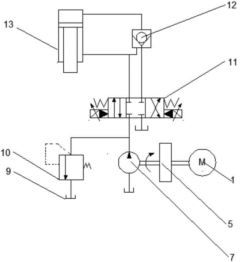
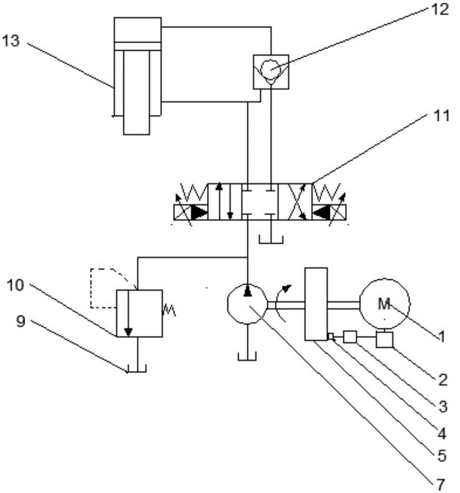
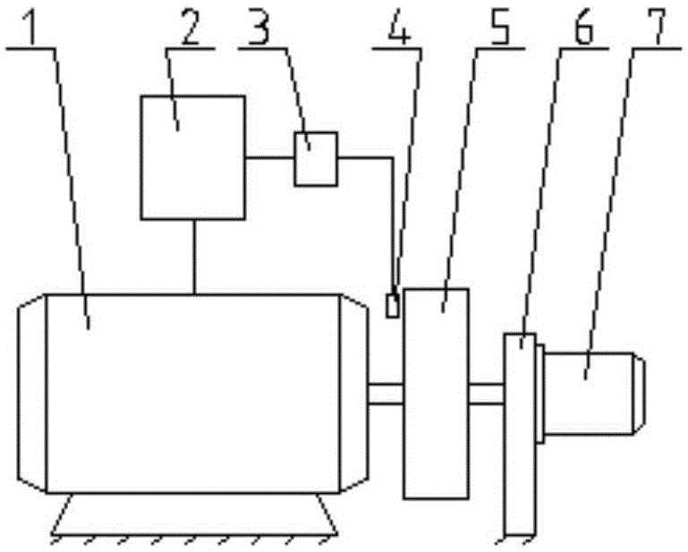
[0030] refer to figure 2 , Figure 3(a) ~ Figure 3(b) , the power plant of the present invention includes a motor 1, an oil pump 7, a flywheel 5, a sensor 4, a frequency converter 2 and a controller 3; wherein the flywheel 5 is connected to the motor 1, and it can store energy when the motor 1 is idling or under low load The sensor 4 is used to collect the flywheel 5 rotating speed; the contr...


PUM


Abstract

The invention discloses a power device used for reducing installed power of a hydraulic machine. The power device comprises an electromotor, a frequency converter, a controller, a rotation speed sensor, an oil pump and a flywheel, wherein the electromotor is sequentially connected with the frequency converter, the controller and the sensor; the flywheel and the oil pump are installed on a rotary shaft of the electromotor; the sensor is used for collecting the rotation speed of the flywheel and transmitting the rotation speed to the controller; the controller is used for receiving the rotation speed of the sensor and controlling the output voltage and the output frequency of the frequency converter according to the rotation speed signal so as to adjust the frequency and each phase of voltage of an electromotor stator winding when the rotation speed of the flywheel is decreased, so that the frequency and each phase of voltage of the electromotor stator winding adapts to the rotation speed of the rotary shaft of the electromotor. The stored energy of the flywheel is utilized firstly, energy is released in the working feed stage, the controller is used for achieving synchronous change of the given rotation speed of the electromotor and the rotation speed of the flywheel, the changes of the rotation speed of the electromotor are controlled accurately, the installed power of the electromotor is greatly reduced and the purpose of energy conservation is achieved.

Description

technical field [0001] The invention relates to the field of hydraulic machines, more specifically, to a power device for reducing the installed power of a hydraulic machine and its application. Background technique [0002] The hydraulic machine generally adopts the direct transmission of the oil pump, and the motor directly drives the oil pump to work. The oil pump converts the mechanical energy into the pressure energy of the oil, and drives the slider to move through the hydraulic cylinder to complete the work. Generally, a complete working cycle of a hydraulic press consists of the following four stages: fast down stage (filling liquid in the liquid filling device, rapid empty travel of the slider downward), working stage (slow speed work pressurization, sometimes there is pressure holding , In the working stage, the working pressure of the hydraulic press increases with the degree of deformation of the workpiece), the return stage and the stop stage. The moving speed ...

Claims


Application Information

Patent Timeline
Patent Type & Authority Applications(China)
IPC IPC(8): B30B15/16B30B15/26
Inventor 陈柏金罗琬先潘玉晶
Owner HUAZHONG UNIV OF SCI & TECH
Why Eureka
Try Eureka