Fresh air heat recovery method and equipment

A technology of fresh air heat recovery and fresh air, applied in heating methods, ventilation systems, piping arrangements, etc., can solve the problems of inability to achieve full heat recovery rate, expensive model materials, limited recovery efficiency, etc., to improve the quality of life and cost. Low and energy saving effect

Inactive Publication Date: 2005-10-26
蒋国良
View PDF4 Cites 10 Cited by
  • Summary
  • Abstract
  • Description
  • Claims
  • Application Information

AI Technical Summary

Problems solved by technology

The total heat recovery rate of these two heat recovery devices is about 70%, and is generally suitable for occasions with a large fresh air volume. Although the former also has a small air volume model, the material cost of the model is expensive, and the total heat recovery efficiency is at most about 79%.
The latter sprays a large amount of liquid and must be equipped with a circulation pump and a solution tank. The device has a large volume and high cost
The application number is 200310122814.4 "Dividing wall solvent medium total heat recovery method and device" is to use the solution to circulate in the air duct to achieve the purpose of heat recovery, heat and moisture are transferred by the solution flowing between the fresh air duct and the exhaust duct , this method must be equipped with a circulation pump and a solution tank, the device is large in size, high in cost, and the recovery efficiency is limited
The patent application with application number 200410017627.4 discloses "a highly efficient gas total heat recovery and energy conversion method", which actually cannot achieve the total heat recovery rate greater than 100% as it says, because there is no perpetual motion machine in the world, After one kind of energy is converted into another kind of energy, the amount cannot be greater than the original amount, and this method also has the disadvantages of high cost and complicated structure
[0007] From the above analysis, it can be seen that the existing fresh air heat recovery methods and devices have the above disadvantages, such as low heat recovery rate, high cost, large volume, and only suitable for large flow occasions, etc.

Method used


Image

  • Fresh air heat recovery method and equipment
  • Fresh air heat recovery method and equipment
  • Fresh air heat recovery method and equipment

Examples


Embodiment 1

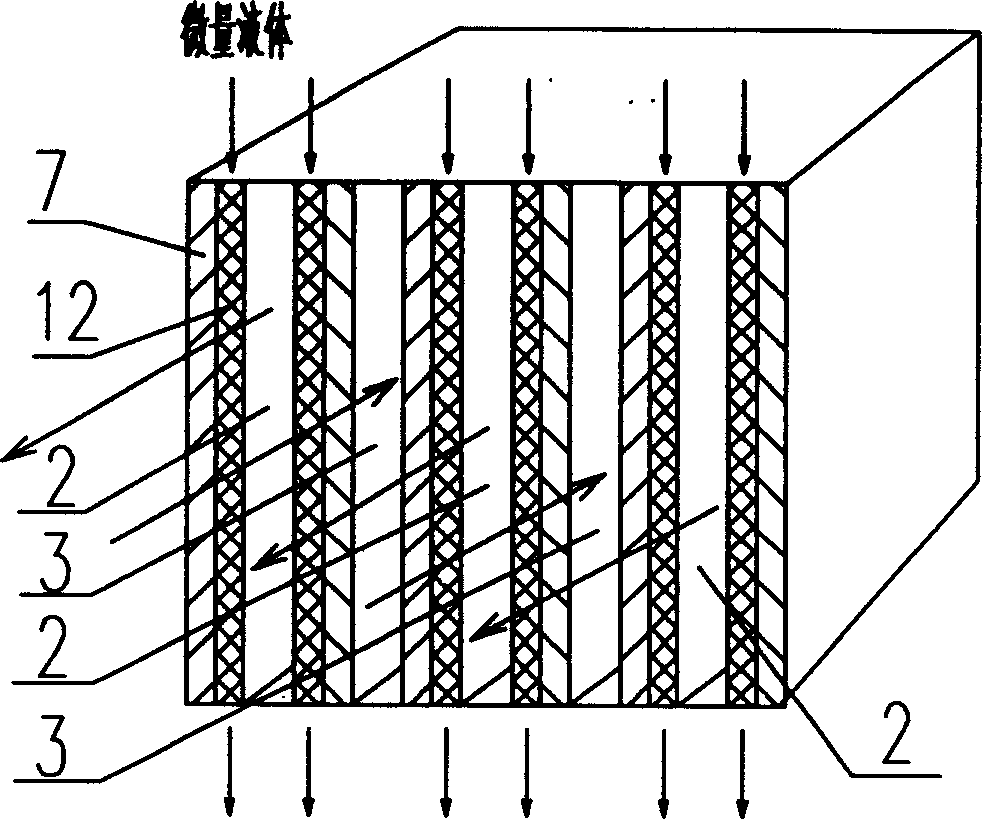
[0035] see figure 1A number of air duct plates 7 are used to isolate several exhaust ducts 2 and new air ducts 3, the exhaust ducts 2 and the new air ducts 3 are arranged at intervals, and a liquid-wetting layer is arranged on the surface of the air duct plates 7 located on the side of the exhaust duct 12. During cooling, a small amount of liquid flows into the liquid-wetting layer 12 from the upper part of the liquid-wetting layer 12 in the direction shown in the figure, and then spreads to various parts of the liquid-wetting layer 12, wherein part of the liquid evaporates into the exhaust duct 2, and the remaining liquid flows from The lower part of the liquid wetting layer 12 flows out. Since the surface temperature of the air duct plate 7 on the side of the exhaust duct is close to the wet bulb temperature of the exhaust air, through heat conduction, the surface temperature of the air duct plate 7 on the side of the new air duct is close to the surface temperature of the ...

Embodiment 2

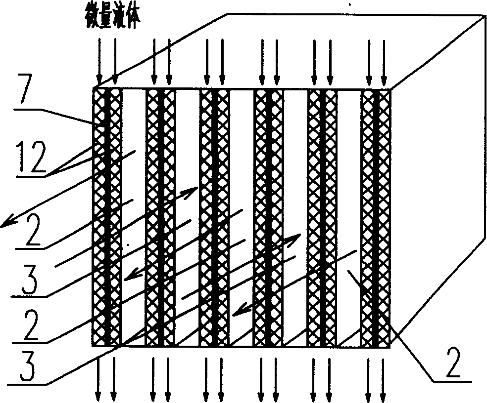
[0037] see figure 2 , use some air duct plates 7 to isolate into several exhaust ducts 2 and new air ducts 3, the exhaust ducts 2 and the new air ducts 3 are arranged at intervals, and the surfaces of the air duct plates 7 on the side of the new air duct and on the side of the exhaust duct Liquid-wetting layers 12 are provided on both sides of the air channel plate 7 , that is, liquid-wetting layers 12 are provided on both sides of the air duct plate 7 . During cooling, a small amount of liquid flows into the liquid-wetting layer 12 from the upper part of the liquid-wetting layer 12 in the direction shown in the figure, diffuses to various parts of the liquid-wetting layer 12, and part of the liquid evaporates into the exhaust air in the exhaust air channel 2, and the remaining liquid Flowing out from the lower part of the liquid-wetting layer 12, the surface temperature of the air channel plate 7 on the side of the exhaust air channel 2 is close to the wet bulb temperature o...

Embodiment 3

[0050] see Figure 10 ~ Figure 11 , compared with Embodiment 1, the arrangement direction of the air duct plates 7 in this embodiment is different, and the air duct plates 7 are arranged vertically; Hole, its structure is simpler than embodiment 1, and all the other structures are the same.


PUM


Abstract

The invention relates to the air treatment method and the device, especially to the new wind heat recycling method and its device. The method has the new air passage and the exhaust passage separated by the air passage plate; the liquid soakage layer of the said plate at the exhaust passage side; the minim liquid flows in or on the soakage layer when refrigeration to realize the heat exchange between the new air passage and the exhaust passage; the temperature difference between the new air passage and the exhaust passage realizes the heat exchange when heating. The device comprises the air passage wall, the new air intake, the new air outtake, the exhaust intake, the exhaust outtake, the new air passage and the exhaust passage, also the liquid intake, the liquid arranging structure connecting the liquid intake, and the soakage layer of the air passage plate at the side of the exhaust passage. The invention has high heat recycling ratio and wide utilization.

Description

technical field [0001] The invention relates to an air treatment method and its device, in particular to a fresh air heat recovery method and its device for air-conditioning equipment. Background technique [0002] In order to meet the requirements of comfort, modern buildings generally install air-conditioning equipment. In order to improve the indoor air quality, air-conditioned rooms need to properly introduce fresh air. [0003] At present, there are mainly the following methods for dealing with fresh air: [0004] 1. The outdoor fresh air is directly pumped into the room, and the indoor air is directly discharged to the outside. There is no energy recovery device installed between the two air streams. Due to the simple structure of this method, most of the current air-conditioning systems adopt this method. The disadvantage of this method is that it consumes a lot of energy, and the energy consumption of fresh air accounts for 25% to 40% of the total energy consumptio...

Claims


Application Information

Patent Timeline
Patent Type & Authority Applications(China)
IPC IPC(8): F24F1/0043F24F5/00F24F7/08
CPCF24F2001/0092Y02B30/545F24F5/0035F24F1/0007Y02B30/54F24F1/0043
Inventor 蒋国良
Owner 蒋国良
Why Eureka
Try Eureka