Cooling mechanism of injection mold

A technology of heat dissipation mechanism and injection mold, applied in the field of mold, can solve the problems of slow cooling speed and water residue affecting the service life of injection mold, and achieve the effect of improving heat dissipation speed

Inactive Publication Date: 2020-03-06
齐雨光
View PDF7 Cites 2 Cited by
  • Summary
  • Abstract
  • Description
  • Claims
  • Application Information

AI Technical Summary

Problems solved by technology

[0004] The purpose of the present invention is to provide a heat dissipation mechanism of an injection mold, which has the advantage of common heat dissipation inside and outside, and solves the problem that modern injection molds often use water to cool the mold cavity in order to speed up the molding speed in the mold cavity, but this method is easy. A large amount of water residue affects the service life of the injection mold, and the single cooling method leads to the problem of slow cooling speed

Method used


Image

  • Cooling mechanism of injection mold
  • Cooling mechanism of injection mold
  • Cooling mechanism of injection mold

Examples


Embodiment Construction

[0029] The following will clearly and completely describe the technical solutions in the embodiments of the present invention with reference to the accompanying drawings in the embodiments of the present invention. Obviously, the described embodiments are only some, not all, embodiments of the present invention. Based on the embodiments of the present invention, all other embodiments obtained by persons of ordinary skill in the art without making creative efforts belong to the protection scope of the present invention.

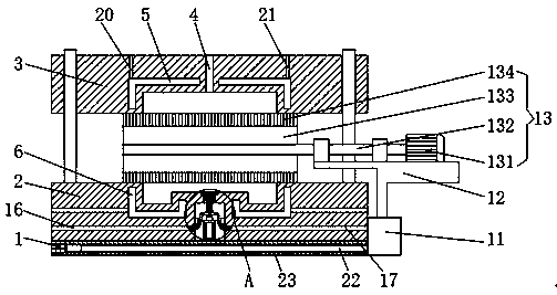
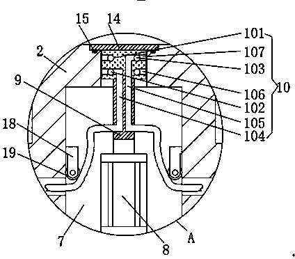
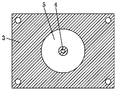
[0030] see Figure 1-6 , a heat dissipation mechanism for an injection mold, comprising a bottom plate 1, a fixed module 2 is fixedly connected to the top of the bottom plate 1, a moving module 3 is arranged on the top of the fixed module 2, an injection hole 4 is opened on the top of the moving module 3, and the top of the moving module 3 There is a first water-cooling heat dissipation groove 5 inside, and a second water-cooling heat dissipation groove 6 is a...


PUM


Abstract

The invention discloses a cooling mechanism of an injection mold. The cooling mechanism comprises a bottom plate, a fixed mold block is fixedly connected to the top of the bottom plate, a movable moldblock is arranged on the top of the fixed mold block, an injection molding hole is formed in the top of the movable mold block, and a first water cooling groove is formed in the movable mold block. Through the bottom plate, the fixed mold block, the movable mold block, the injection molding hole, the first water cooling groove, a second water cooling groove, a containing groove, an air cylinder,an ejector rod, a water cooling and air cooling mixed cooling mechanism, a fixed block, a supporting frame and an air cooling mechanism, the problems that a modern injection mold often uses water forcooling a mold cavity in order to quicken the forming speed in the mold cavity, the manner easily causes residue of a large amount of water, and the service life of the injection mold is affected aresolved, meanwhile, the problem that the single cooling manner causes slow cooling speed is solved, and the cooling mechanism of the injection mold has the advantage of inner and outer joint cooling, and the improves the cooling speed.

Description

technical field [0001] The invention relates to the technical field of molds, in particular to a heat dissipation mechanism of an injection mold. Background technique [0002] Injection molding is a tool for producing plastic products, and it is also a tool for giving plastic products a complete structure and precise dimensions. Injection molding is a processing method used in the mass production of certain complex-shaped parts. Specifically, it refers to melting plastic by heat. The injection molding machine injects into the mold cavity under high pressure, and after cooling and solidifying, the molded product is obtained. [0003] In order to speed up the molding speed in the mold cavity, modern injection molds often use water to cool the mold cavity, but this method is prone to a large amount of water residue and affects the service life of the injection mold. At the same time, the heat dissipation reduces the heat dissipation speed and increases the interval time of inj...

Claims


Application Information

Patent Timeline
Patent Type & Authority Applications(China)
IPC IPC(8): B29C45/26B29C45/40B29C45/73B29C45/17
CPCB29C45/1753B29C45/2602B29C45/4005B29C45/7312
Inventor 齐雨光
Owner 齐雨光
Why Eureka
Try Eureka