Customized lifting appliance of cable reel

A cable reel and spreader technology, applied in the field of spreaders, can solve the problems of poor protection of cables, large swing range of cable reels in the air, hidden dangers of on-site operation safety, etc., to reduce aisles and work space Position, reduced hoisting time, simple and convenient use

Pending Publication Date: 2020-03-06
NINGBO POWER SUPPLY COMPANY STATE GRID ZHEJIANG ELECTRIC POWER
View PDF0 Cites 0 Cited by
  • Summary
  • Abstract
  • Description
  • Claims
  • Application Information

AI Technical Summary

Problems solved by technology

[0002] At present, the cable material storage operation adopts automobile hoisting and driving hoisting, and most of the operations are performed by steel wire ropes. Due to the action of tension, the steel wire ropes will be squeezed inward during the lifting process; deformation, or even scrapping the cable reel; at the same time, there are many disadvantages in the actual operation of the existing cable reel hoisting method using wire ropes, the specific problems are as follows:
[0003] (1) For safety reasons, steel wire ropes are generally relatively thick, because the diameter is directly proportional to the pulling force, and the convenience is very poor when the operator is working, especially in the process of crossing the cable reel because the steel wire rope sags due to gravity, The operator needs to penetrate multiple times to reach the expected position;
[0004] (2) At present, the position of the single-rope hoisting cable reel will be shifted during the lifting operation, which will cause the cable reel to swing too much in the air, which will pose a safety hazard to the on-site operation;
[0005] (3) After the cable reel is squeezed and deformed due to inward pressure, it is difficult to get out of the cable under working conditions, and it cannot protect the cable well

Method used


Image

  • Customized lifting appliance of cable reel
  • Customized lifting appliance of cable reel

Examples


Embodiment Construction

[0024] In the description of this embodiment, it should be noted that if the terms "center", "upper", "lower", "left", "right", "vertical", "horizontal", "inner", " Outside", "front", "rear", etc., the orientation or positional relationship indicated is based on the orientation or positional relationship shown in the drawings, which is only for the convenience of describing the present invention and simplifying the description, rather than indicating or implying Any device or element must have a specific orientation, be constructed and operate in a specific orientation and, therefore, should not be construed as limiting the invention. In addition, the terms "first", "second", and "third" are used for descriptive purposes only, and should not be understood as indicating or implying relative importance.

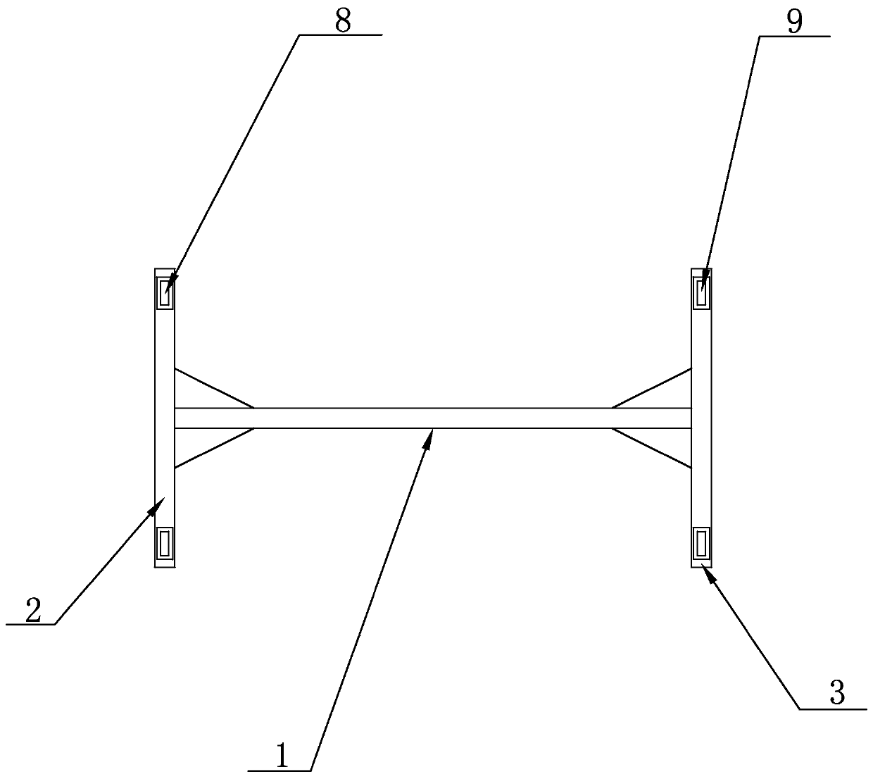
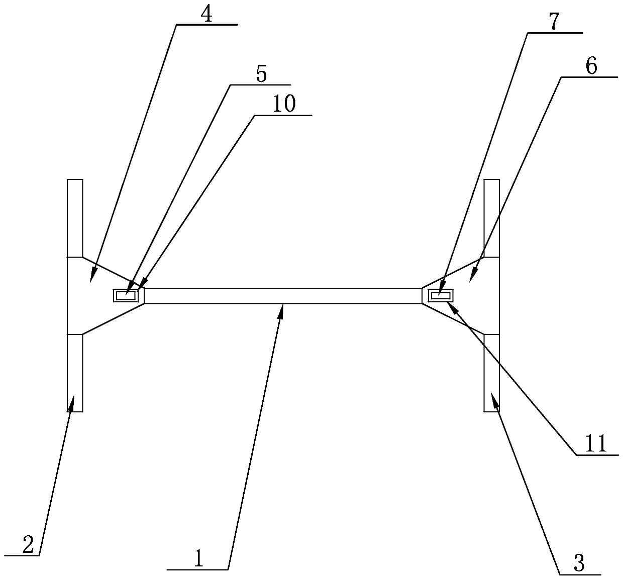
[0025] see figure 1 with figure 2 , a cable reel custom-made sling disclosed in the present invention, comprising a suspension beam main body 1, one end of the suspension be...


PUM


Abstract

The invention discloses a customized lifting appliance of a cable reel. The customized lifting appliance of the cable reel comprises a lifting beam body. One end of the lifting beam body is fixedly provided with a first locating side beam. The other end of the lifting beam body is fixedly provided with a second locating side beam. The first locating side beam, the lifting beam body and the secondlocating side beam jointly constitute an H-shaped structure. A first reinforcing rib plate is arranged on the first locating side beam and located at the left end of the upper end face of the liftingbeam body. A first lifting lug is fixedly arranged on the upper end face of the first reinforcing rib plate. A second reinforcing rib plate is fixedly arranged on the second locating side beam and located at the right end of the upper end face of the lifting beam body. A second lifting lug is fixedly arranged on the upper end face of the second reinforcing rib plate. According to the technical scheme, the customized lifting appliance of the cable reel is reasonable in structural design, simple in structure and reliable in work, and the customized lifting appliance of the cable reel can avoid the situation that a cable reel and a cable are squeezed and damaged in the lifting process, shortens loading and unloading time and improves the site utilization ratio.

Description

technical field [0001] The invention relates to the technical field of slings, in particular to a custom-made sling for cable reels. Background technique [0002] At present, the cable material storage operation adopts automobile hoisting and driving hoisting, and most of the operations are performed by steel wire ropes. Due to the action of tension, the steel wire ropes will be squeezed inward during the lifting process; deformation, or even scrapping the cable reel; at the same time, there are many disadvantages in the actual operation of the existing cable reel hoisting method using wire ropes, the specific problems are as follows: [0003] (1) For safety reasons, steel wire ropes are generally relatively thick, because the diameter is directly proportional to the pulling force, and the convenience is very poor when the operator is working, especially in the process of crossing the cable reel because the steel wire rope sags due to gravity, The operator needs to penetrat...

Claims


Application Information

Patent Timeline
Patent Type & Authority Applications(China)
IPC IPC(8): B66C1/22B66C13/06
CPCB66C1/22B66C13/06
Inventor 岳衡骆国荣薛娟萍
Owner NINGBO POWER SUPPLY COMPANY STATE GRID ZHEJIANG ELECTRIC POWER
Why Eureka
Try Eureka