
Draught fan for metal smelting

A metal smelting and fan technology, applied in furnaces, lighting and heating equipment, furnace components, etc., can solve the problems of affecting hot air transportation, reducing the service life of components, and increasing the temperature of components, so as to improve the efficiency of water spraying and prolong the service life , the effect of improving efficiency

Active Publication Date: 2019-05-31
临沂正祥建材有限公司
View PDF5 Cites 3 Cited by
  • Summary
  • Abstract
  • Description
  • Claims
  • Application Information

AI Technical Summary

Problems solved by technology

However, when this type of blower is cooling, it cannot cool the components that are directly in contact with the hot air, thus increasing the temperature of the components, reducing the service life of the components, and easily causing stagnation of air supply, affecting the normal operation of conveying hot air

Method used


Image

  • Draught fan for metal smelting
  • Draught fan for metal smelting
  • Draught fan for metal smelting

Examples


Embodiment Construction

[0029] In order to make the technical means, creative features, goals and effects achieved by the present invention easy to understand, the present invention will be further described below in conjunction with specific embodiments.

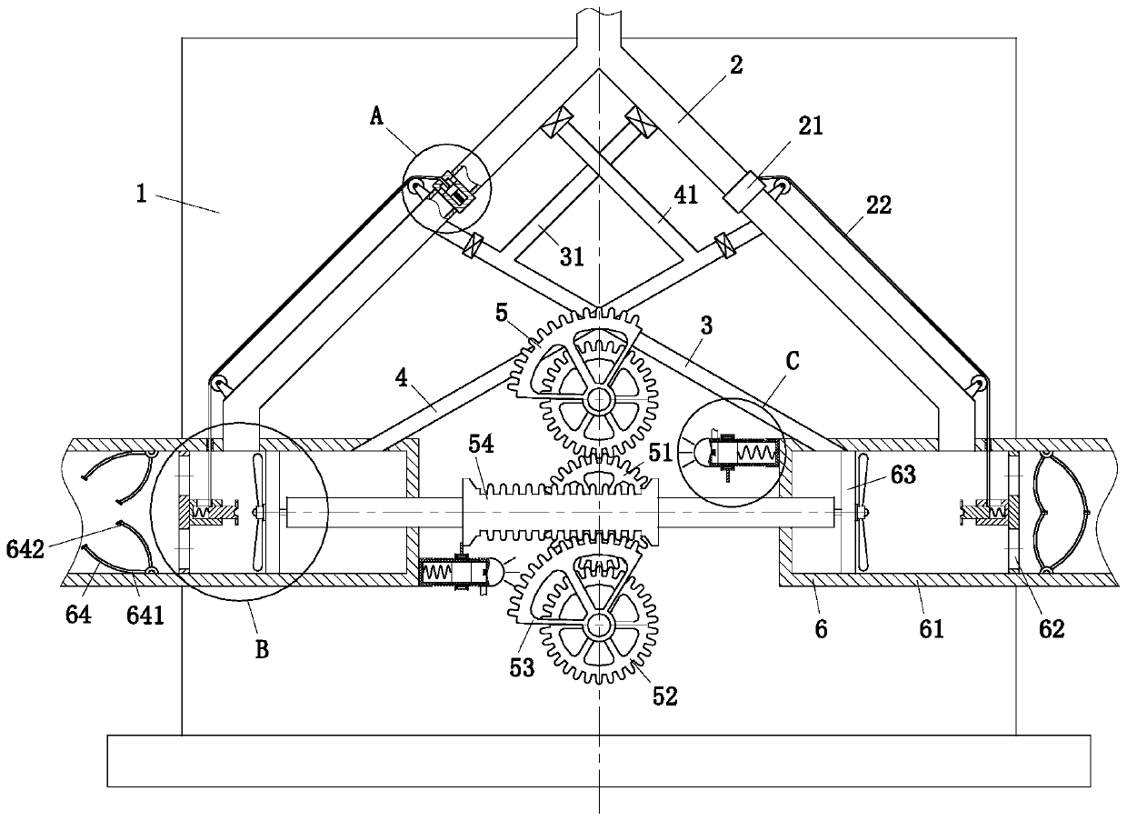
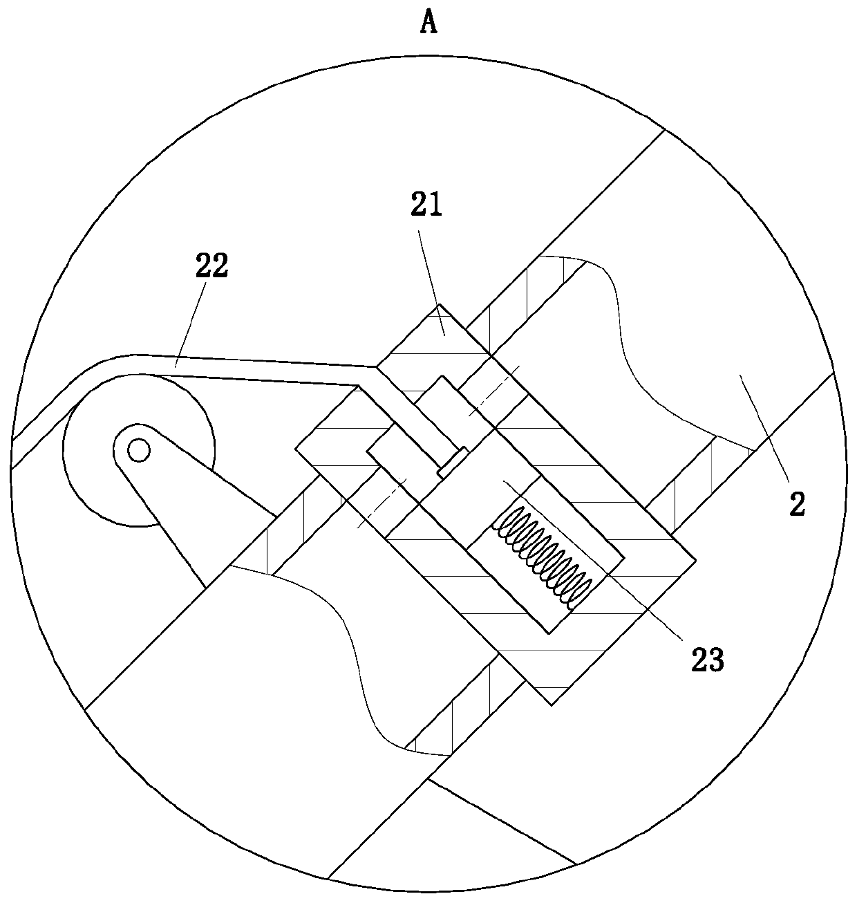
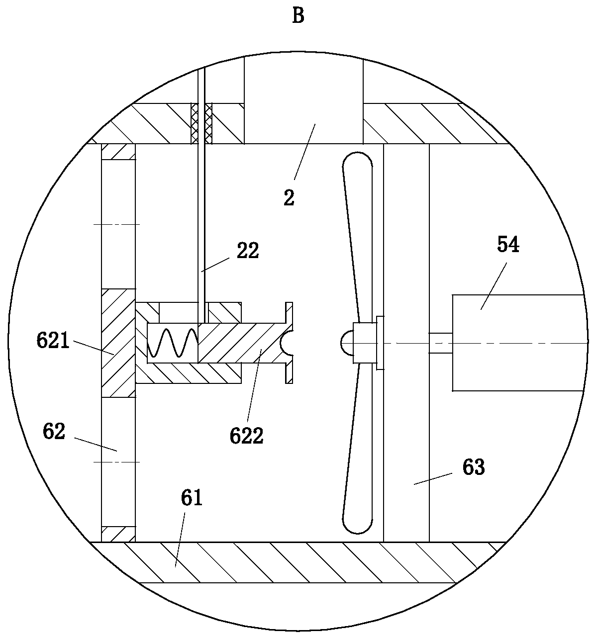
[0030] Such as Figure 1 to Figure 5 As shown, a fan for metal smelting includes a frame 1, a three-way air guide pipe 2, a transmission module 5 and an air supply module 6; the front side of the frame 1 is equipped with a transmission module 5, and the front side of the frame 1 is located at Two air supply modules 6 are installed on both sides of the transmission module 5, and the front side of the frame 1 is located above the transmission module 5, and a three-way air guide pipe 2 is installed, and the two side arms of the three air guide pipe 2 are connected with the two air supply modules 6 respectively. Communication, the rear side of the frame 1 is equipped with a motor, and the motor is connected to the transmission module 5; the transmissi...


PUM


Abstract

The invention belongs to the technical field of draught fans and particularly relates to a draught fan for metal smelting. The draught fan comprises a rack, a three-way air guiding tube, a transmission module and two air supply modules, wherein the transmission module is mounted on the front side of the rack; the two air supply modules are mounted on the two sides of the transmission module and onthe front side of the rack; the three-way air guiding tube is mounted above the transmission module and on the front side of the rack; the two side arms of the three-way air guiding tube communicatewith the two air supply modules separately; a motor is mounted on the rear side of the rack and is in transmission connection with the transmission module; the transmission module comprises a drivingwheel, a driven wheel, a two-sided rack and an arc-shaped gear wheel; the two ends of the two-sided rack extend into the two air supply modules separately; and a thread disc, a switch unit and a closing unit are sequentially arranged in each of two air supply tubes. The draught fan utilizes the air supply tubes to discharge hot-blast air in an uninterrupted manner; and in addition, the two air supply tubes convey the air alternately, so that cooling of the air supply tubes is facilitated, the service life of the air supply tubes is prolonged, and normal hot-blast air supply operation is ensured.

Description

technical field [0001] The invention belongs to the technical field of fans, in particular to a fan for metal smelting. Background technique [0002] The fan is a machine that relies on the input mechanical energy to increase the gas pressure and discharge the gas. It is a driven fluid machine. Fan is the customary abbreviation for gas compression and gas conveying machinery in China. Usually, fans include ventilators, blowers, and wind generators. Fans are mainly used in metallurgy, petrochemical, electric power, urban rail transit, textile, shipbuilding and other fields of national economy and ventilation in various places. During metal smelting, it is necessary to use a fan to introduce hot air into the burner. [0003] There are also some technical solutions for fans in the prior art. For example, a Chinese patent with application number 2016108181396 discloses an externally driven heat-insulated and high-temperature-resistant suction fan, which is welded with an "L"-s...

Claims


Application Information

Patent Timeline
IPC IPC(8): F27D7/02
Inventor 不公告发明人
Owner 临沂正祥建材有限公司
Learn More