Electro-hydraulic gyrator with good heat dissipation effect and adjusting function

A heat dissipation effect and gyrator technology, applied in transmission devices, fluid transmission devices, fluid pressure actuation devices, etc., can solve problems such as easy heat generation, overheating of oil temperature, increased gap between gears and racks, etc., to achieve extended use Long life, avoiding excessive wear, and avoiding the effect of oil temperature overheating

Inactive Publication Date: 2020-03-06
广州京海科技有限公司
View PDF6 Cites 6 Cited by
  • Summary
  • Abstract
  • Description
  • Claims
  • Application Information

AI Technical Summary

Problems solved by technology

[0003] When the existing electro-hydraulic gyrator is working, the hydraulic oil in the oil storage tank tends to generate heat, which leads to overheating of the oil temperature, thereby affecting the normal operation of the existing electro-hydraulic gyrator. Not only that, the existing electro-hydraulic gyrator When the hydraulic gyrator is working, the rack and the gear are in a state of constant friction, which is extremely easy to wear, resulting in an increase in the gap between the gear and the rack, which affects the transmission effect of the gear and the rack, thereby affecting the normal operation of the equipment. Greatly reduces the practicality of the existing electro-hydraulic gyrator

Method used


Image

  • Electro-hydraulic gyrator with good heat dissipation effect and adjusting function
  • Electro-hydraulic gyrator with good heat dissipation effect and adjusting function
  • Electro-hydraulic gyrator with good heat dissipation effect and adjusting function

Examples


Embodiment Construction

[0024] The present invention is described in further detail now in conjunction with accompanying drawing. These drawings are all simplified schematic diagrams, which only illustrate the basic structure of the present invention in a schematic manner, so they only show the configurations related to the present invention.

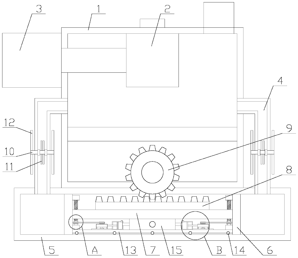
[0025] like figure 1 As shown, an electro-hydraulic gyrator with a good heat dissipation effect and an adjustment function includes an oil storage tank 1, a motor 3, a gear pump 2, a gear 9, a rack 8, an oil cylinder 5, a connecting plate 7, two oil pipes 4 and Two pistons 6, the motor 3 is fixed on the oil storage tank 1, the gear pump 2 is fixed on the top of the oil storage tank 1, the motor 3 is connected to the gear pump 2, and the oil cylinder 5 is horizontally fixed on the oil storage tank 1 Below, the piston 6 is arranged inside the oil cylinder 5, the connecting plate 7 is arranged between the two pistons 6, the rack 8 is fixed above the connecting p...


PUM


Abstract

The invention relates to an electro-hydraulic gyrator with a good heat dissipation effect and an adjusting function. The electro-hydraulic gyrator includes an oil storage tank, a motor, a gear pump, agear, a rack, an oil cylinder, a connection plate, two oil pipes and two pistons. Heat dissipation mechanisms each include a rotating shaft, two first bearings, two rotating assemblies and a plurality of paddles. An adjusting mechanism includes a supporting plate, an air bag, two adjusting assemblies and two inflatable assemblies. According to the electro-hydraulic gyrator with the good heat dissipation effect and the adjusting function, air flow around the oil pipes is accelerated through the heat dissipation mechanisms, heat of the oil pipes is taken away, the function of heat dissipation is realized, and the situation that normal work is affected due to overheating of the oil temperature is avoided; and the adjusting mechanism drives the connection plate to move upward, so that the rack is moved in the direction close to the gear, the gap is reduced, and the situation that the transmission effect is affected due to large gap caused by excessive wear is avoided.

Description

technical field [0001] The invention relates to the field of electro-hydraulic gyrators, in particular to an electro-hydraulic gyrator with an adjustment function and a good heat dissipation effect. Background technique [0002] The electro-hydraulic gyrator is a new type of angular rotary power device. It uses a hydraulic cylinder as the main body and is composed of an electric motor, an oil pump, an oil circuit shunt, a rack, a gear, and a rotating shaft. When the piston reciprocates, the integrated The rack drives the gear to swing back and forth between 0-90 degrees and 0-120 degrees. [0003] When the existing electro-hydraulic gyrator is working, the hydraulic oil in the oil storage tank tends to generate heat, which leads to overheating of the oil temperature, thereby affecting the normal operation of the existing electro-hydraulic gyrator. Not only that, the existing electro-hydraulic gyrator When the hydraulic gyrator is working, the rack and the gear are in a stat...

Claims


Application Information

Patent Timeline
Patent Type & Authority Applications(China)
IPC IPC(8): F15B11/08F15B21/0423F15B21/08F16H47/02
CPCF15B11/08F15B21/08F16H47/02F15B21/0423
Inventor 王彩霞
Owner 广州京海科技有限公司
Why Eureka
Try Eureka