A method for detecting residual energy of a battery module

A battery module and detection method technology, which is applied in the direction of measuring electricity, measuring devices, and measuring electrical variables, etc., can solve the problems of high demand for testing instruments and high time and cost of residual energy detection, and achieve long-term solutions. Effect of discharge rate reduction

Active Publication Date: 2022-06-07
SHANGHAI UNIVERSITY OF ELECTRIC POWER
View PDF11 Cites 0 Cited by
  • Summary
  • Abstract
  • Description
  • Claims
  • Application Information

AI Technical Summary

Problems solved by technology

[0004] According to the "Residual Energy Detection of Vehicle Power Battery Recycling and Utilization" (GB / T34015-2017) standard issued by the National Standards Committee of China, I 5 The current capacity is calibrated for 3-5 times. When the capacity difference of 3 consecutive times is less than 3% of the rated capacity, the experiment can be ended. Among them, constant current charging and constant voltage charging are required for capacity calibration. After each calibration The static time is not more than 1 hour, so the residual energy detection process of a battery cell or battery module in the greenhouse needs to occupy a detection instrument for 36 to 60 hours, which will undoubtedly lead to high time and cost of residual energy detection. The need for more testing instruments and other issues

Method used


Image

  • A method for detecting residual energy of a battery module
  • A method for detecting residual energy of a battery module
  • A method for detecting residual energy of a battery module

Examples


Embodiment Construction

[0043] The present invention will be described in detail below with reference to the accompanying drawings and specific embodiments.

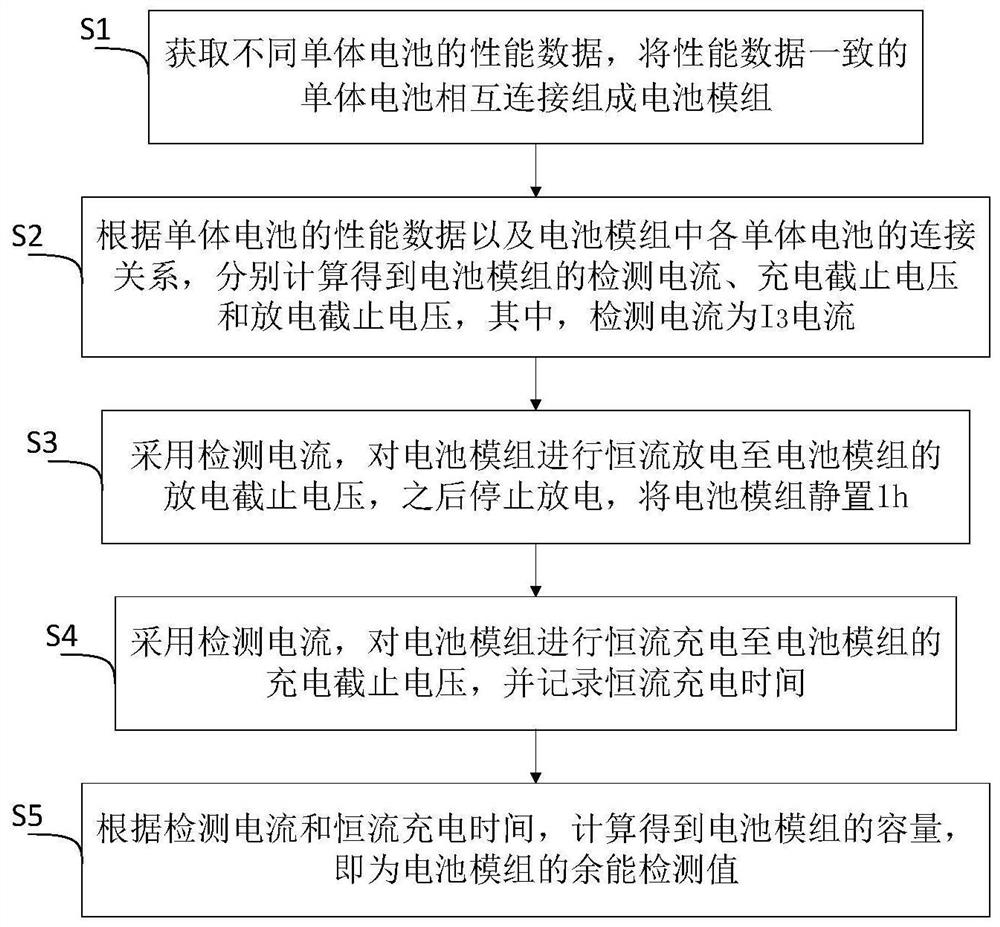
[0044] like figure 1 As shown, a method for detecting residual energy of a battery module includes the following steps:

[0045] S1. Obtain performance data of different single cells, and connect cells with consistent performance data to form a battery module;

[0046] S2, according to the performance data of the single cell and the connection relationship of each single cell in the battery module, calculate the detection current, charge cut-off voltage and discharge cut-off voltage of the battery module respectively, wherein the detection current is I 3 current;

[0047] S3. Use the detection current to discharge the battery module with constant current to the discharge cut-off voltage of the battery module, then stop the discharge, and let the battery module stand for 1h;

[0048] S4. Use the detection current to charge the battery module ...


PUM


Abstract

The invention relates to a method for detecting residual energy of a battery module, comprising: S1, obtaining performance data of different single batteries, and connecting single batteries with consistent performance data to form a battery module; S2, according to the performance data of the single batteries And the connection relationship of each single battery in the battery module, the detection current, charge cut-off voltage and discharge cut-off voltage of the battery module are obtained respectively, wherein, the detection current is I 3 current; S3, using the detection current, discharge the battery module with a constant current to the discharge cut-off voltage of the battery module, then stop discharging, and leave the battery module for 1 hour; S4, use the detection current, discharge the battery module with a constant current Charge to the charging cut-off voltage of the battery module, and record the constant current charging time; S5, obtain the capacity of the battery module according to the detected current and the constant current charging time, which is the residual energy detection value of the battery module. Compared with the prior art, the invention shortens the residual energy detection time on the basis of ensuring the accuracy.

Description

technical field [0001] The invention relates to the technical field of storage batteries, in particular to a method for detecting residual energy of a battery module. Background technique [0002] In recent years, there has been a significant increase in the number of pure electric vehicles, which are considered to be the best alternative to conventional vehicles for dealing with global warming and environmental pollution. Lithium-ion batteries have become one of the main power sources for electric vehicles due to their high efficiency, high specific energy and long service life. However, the growing demand and production of lithium-ion batteries will raise issues of battery recycling and disposal in the coming years. [0003] Usually, the average service life of a power battery is 5-8 years, and its performance decays with the increase of charging times. When the battery capacity decays to less than 80% of the rated capacity, the power battery is no longer suitable for ele...

Claims


Application Information

Patent Timeline
Patent Type & Authority Patents(China)
IPC IPC(8): G01R31/385G01R31/396
CPCG01R31/385G01R31/396
Inventor 廖强强李新周谭轶童刘鑫鑫周豪磊
Owner SHANGHAI UNIVERSITY OF ELECTRIC POWER
Why Eureka
Try Eureka