
Remote control device for smart micro-grid system based on bifurcation theory

A technology for remote control devices and micro-grids, applied in circuit devices, substation/distribution device casings, electrical components, etc., can solve problems such as a large amount of energy loss, damage to energy storage devices, and different energy times, and prevent efficiency from falling. Effect

Inactive Publication Date: 2020-03-06
南京鑫宜科技有限公司
View PDF5 Cites 0 Cited by
  • Summary
  • Abstract
  • Description
  • Claims
  • Application Information

AI Technical Summary

Problems solved by technology

[0004] The technology of each device in the traditional micro-grid has matured, but since the micro-grid is composed of distributed power sources, the transmission distance and type of each power source are different, resulting in different time for them to store full energy, while the existing micro-grid The power grid does not set up a corresponding power supply control device for this phenomenon. As a result, when an energy storage device is full of energy, the current cannot be remotely controlled to flow to the next storage device, resulting in a large amount of energy loss and damage to the energy storage device. Therefore, a remote control device for smart microgrid system based on bifurcation theory came into being

Method used

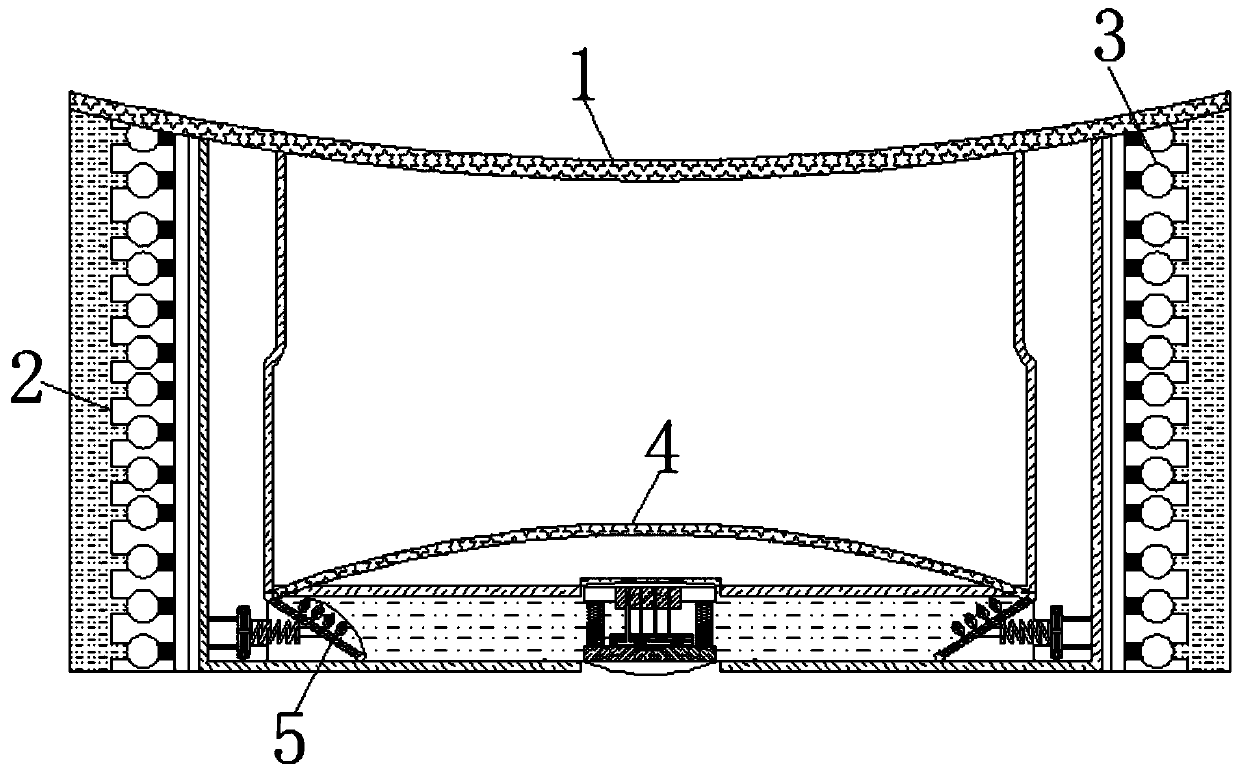

Image

  • Remote control device for smart micro-grid system based on bifurcation theory
  • Remote control device for smart micro-grid system based on bifurcation theory
  • Remote control device for smart micro-grid system based on bifurcation theory

Examples


Embodiment Construction

[0024] The following will clearly and completely describe the technical solutions in the embodiments of the present invention with reference to the accompanying drawings in the embodiments of the present invention. Obviously, the described embodiments are only some of the embodiments of the present invention, not all of them. Based on the embodiments of the present invention, all other embodiments obtained by persons of ordinary skill in the art without making creative efforts belong to the protection scope of the present invention.

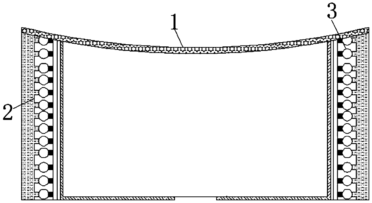
[0025] see Figure 1-7 , a remote control device for a smart microgrid system based on bifurcation theory, including a housing 1, an electrolytic cell 2 is fixedly connected to the housing 1, active substances are attached to the surface of the electrolytic cell 2, and the interior of the electrolytic cell 2 is fixedly connected There are electrode plates 3, the number of electrode plates 3 is two and the polarity is opposite, the inner bottom wa...


PUM


Abstract

The invention relates to the technical field of micro-grid remote control, and discloses a remote control device for a smart micro-grid system based on a bifurcation theory. The remote control deviceincludes a housing, wherein the housing is fixedly connected with an electrolytic cell; an electrode plate is fixedly connected in the electrolytic cell; a refracting cover is fixedly connected to theinner bottom wall of the housing; a light source plate is movably connected inside the capsule of the refracting cover; a spring rod is movably connected to the surface of the light source plate; andan end of the spring rod away from the light source plate is movably connected with a flow adjustment plate. In addition, a light beam emitted from a bulb on the surface of the light source plate enters the electrolytic cell from the surface of the refracting cover, and the light of different angles is reflected or refracted on a surface of the refracting cover in contact with a medium. When a certain amount of water gathers, the water is allowed to enter a gas-liquid tank, and a return spring is stretched by the force of a water flow, thereby achieving an effect of automatically replenishinga storage device with water to prevent its efficiency from decreasing.

Description

technical field [0001] The invention relates to the technical field of remote control of micro-grids, in particular to a remote control device for smart micro-grid systems based on bifurcation theory. Background technique [0002] Microgrid, also translated as microgrid, is an autonomous system capable of self-control, protection and management. and so on. [0003] With the reduction of non-renewable energy in the world, people have invented equipment that can use natural energy and convert it into electrical energy, and then transport the electrical energy to energy storage devices through some transportation equipment such as wires for people to use. [0004] The technology of each device in the traditional micro-grid has matured, but since the micro-grid is composed of distributed power sources, the transmission distance and type of each power source are different, resulting in different time for them to store full energy, while the existing micro-grid The power grid do...

Claims


Application Information

Patent Timeline
Patent Type & Authority Applications(China)
IPC IPC(8): H02B1/26H02J13/00
CPCH02B1/26
Inventor 侯琛
Owner 南京鑫宜科技有限公司
Learn More