A method for indoor signal coverage

A signal coverage and radio frequency signal technology, applied in the field of indoor communication, can solve the problems of uneven distribution of radiation signal field strength, limited radiation signal coverage width, poor reception effect of mobile terminals, etc., to achieve good reception effect, wide coverage, Reduce the effect of mutual influence

Active Publication Date: 2022-06-28
内江喜马雅拉网络技术有限公司
View PDF5 Cites 0 Cited by
  • Summary
  • Abstract
  • Description
  • Claims
  • Application Information

AI Technical Summary

Problems solved by technology

[0002] Indoor signal coverage generally adopts an antenna array, which is divided into multiple radiation nodes for signal coverage. Each radiation node is a miniature antenna array. At present, the field strength pattern of the miniature antenna array used is vertical Downward, the coverage width of the field strength of the radiated signal is limited, and the field strength gradually weakens from the middle to both ends in the coverage area, resulting in uneven distribution of the field strength of the indoor radiated signal, and the reception of the mobile terminal Ineffective

Method used


Image

  • A method for indoor signal coverage
  • A method for indoor signal coverage
  • A method for indoor signal coverage

Examples


Embodiment

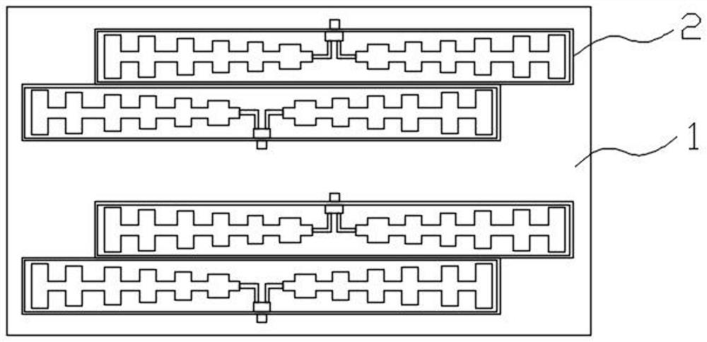
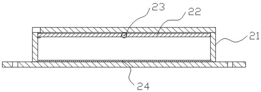
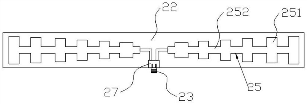
[0043] like Figure 1-Figure 3As shown in the figure, a high-performance antenna array with uniform field strength coverage includes several micro-antenna arrays evenly distributed indoors in node type, and the micro-antenna array includes a mounting plate 1 and a plurality of mutually parallel antennas arranged on the mounting plate 1 2. The antenna 2 includes a housing 21 and a dielectric substrate 22 arranged in the housing 21. One side surface of the dielectric substrate 22 is provided with two first radiating elements 25 distributed in mirror symmetry, so The first radiating element 25 is a strip-shaped radiating element whose width gradually narrows from one end to the other end, and the narrower ends of the two first radiating elements 25 are opposite to each other; There is a radio frequency transmission line joint 23, and the output end of the radio frequency transmission line joint 23 is respectively connected with the narrower ends of the two first radiating element...


PUM


Abstract

The invention discloses an indoor signal coverage method, which comprises the following steps: S1, the radio frequency transmission line joint receives the radio frequency signal from the base station; S2, the power divider divides the radio frequency signal into two beams of equal power signals, and transmits them to the mirror symmetrical Two sets of radiating elements are provided; S3, the first radiating element and the second radiating element on the two sets of radiating elements respectively receive radio frequency signals, and send radiation signals with increasing field strength, forming a rectangular coverage area in the indoor space. The first radiating element and the second radiating element are respectively set on the upper and lower surfaces of the dielectric substrate, which ensures the relative isolation of the two radiating elements and reduces the mutual influence between the two radiating elements, so that the gain of the antenna can be increased to 9‑ 10dbi, meeting the RF field strength coverage requirements of 5G antennas.

Description

technical field [0001] The invention relates to the technical field of indoor communication, in particular to an indoor signal coverage method. Background technique [0002] Indoor signal coverage generally uses antenna arrays, which are divided into multiple radiating nodes for signal coverage. Each radiating node is a miniature antenna array. At present, the micro-antenna array used has a vertical pattern of field strength. Downward, the coverage width of the field strength of the radiated signal is limited, and the field strength in the coverage area gradually becomes weaker from the middle to the two ends, resulting in uneven distribution of the field strength of the indoor radiated signal, and the reception of the mobile terminal Ineffective. SUMMARY OF THE INVENTION [0003] In order to solve the problems existing in the prior art, the present invention provides a high-performance antenna array with uniform field intensity coverage, the coverage width of the radiate...

Claims


Application Information

Patent Timeline
Patent Type & Authority Patents(China)
IPC IPC(8): H04W16/20H01Q1/36H01Q1/38H01Q1/42H01Q21/00
CPCH04W16/20H01Q1/38H01Q1/36H01Q1/42H01Q21/00
Inventor 刘巍滟刘类英冯愉
Owner 内江喜马雅拉网络技术有限公司
Why Eureka
Try Eureka